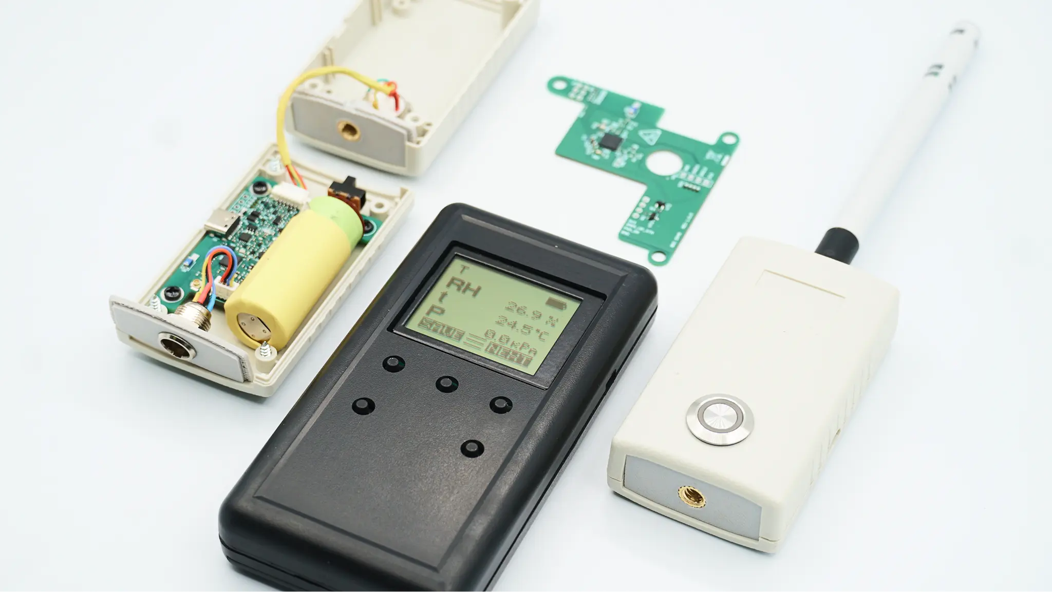
EnCata upgraded an indoor microclimate meter with wireless probes and a redesigned interface. The system measures air temperature, humidity, air velocity, and pressure, with a black globe probe for radiant heat assessment. The original processing unit and algorithms were retained.
The client develops and manufactures instruments for measuring indoor microclimate parameters. These devices are used to assess sanitary, environmental, and technical conditions in residential and industrial buildings, cultural institutions, archives, warehouses, workplaces, and other indoor environments where significant airborne contamination is not expected.
The original instrument consisted of two interconnected parts: a central data processing unit and a measurement unit. The central unit received sensor readings, processed them using established algorithms, and displayed the results on a built-in screen. Wired probes for temperature, humidity, and ultraviolet radiation measurements connected to this unit.
The system had one important limitation: it could work with only one probe at a time. The operator had to connect the appropriate sensor and take measurements at the instrument's location.
The client wanted to introduce wireless measurement capabilities without replacing the existing processing unit or rewriting its proven data processing algorithms.
Challenge
The engineering team faced three main challenges during development.
Retrofitting a wired instrument with wireless connectivity. The instrument already had an established hardware and firmware architecture. We needed to introduce wireless probe communication while retaining the existing processing unit and avoiding major changes to the core measurement workflow.
Preserving the original measurement algorithms. The client wanted to keep the existing environmental data processing algorithms intact. Our task was to introduce a new data source without changing how the instrument interpreted, filtered, and displayed measurements.
Balancing wireless range, battery life, and device size. The wireless modules had to fit into compact, battery-powered enclosures, maintain a reliable BLE connection, and operate throughout extended measurement sessions. Achieving these requirements also meant addressing power consumption, antenna performance, and practical assembly constraints.
Challenges
01
01. Retrofitting a wired instrument with wireless connectivity
The instrument already had an established hardware and firmware architecture. We needed to introduce wireless probe communication while retaining the existing processing unit and avoiding major changes to the core measurement workflow.
02
02. Preserving the original measurement algorithms
The client wanted to keep the existing environmental data processing algorithms intact. Our task was to introduce a new data source without changing how the instrument interpreted, filtered, and displayed measurements.
03
03. Balancing wireless range, battery life, and device size
The wireless modules had to fit into compact, battery-powered enclosures, maintain a reliable BLE connection, and operate throughout extended measurement sessions. Achieving these requirements also meant addressing power consumption, antenna performance, and practical assembly constraints.
Approach & Solution
The client develops and manufactures instruments for measuring indoor microclimate parameters. These devices are used to assess sanitary, environmental, and technical conditions in residential and industrial buildings, cultural institutions, archives, warehouses, workplaces, and other indoor environments where significant airborne contamination is not expected.
The original instrument consisted of two interconnected parts: a central data processing unit and a measurement unit. The central unit received sensor readings, processed them using established algorithms, and displayed the results on a built-in screen. Wired probes for temperature, humidity, and ultraviolet radiation measurements connected to this unit.
The system had one important limitation: it could work with only one probe at a time. The operator had to connect the appropriate sensor and take measurements at the instrument's location.
The client wanted to introduce wireless measurement capabilities without replacing the existing processing unit or rewriting its proven data processing algorithms.
This project was intended as the first step in a broader product upgrade. Rather than redesigning the entire instrument, the client wanted to validate a wireless architecture that could later support further development, potentially including direct data transmission to a mobile application.
The main engineering objective was to establish a wireless link between the existing measurement probes and the client's processing unit.
Each portable module had to read data from an original sensor, package it in the agreed format, and transmit it over Bluetooth Low Energy. A receiver installed inside the main instrument would then pass the readings to the existing firmware as if they had come from a wired probe.
We also had to make the modules rechargeable, compact, and easy to check in operation through visual status indication.
System Architecture: Retrofitting the Existing Processing Unit
Rather than redesigning the main processing unit, we used a spare UART interface already available in its hardware architecture. This interface was originally intended for connecting additional equipment. We developed a dedicated BLE expansion board, or shield, that could be installed inside the existing instrument through this interface.
The BLE shield handled the wireless communication. It scanned for recognized measurement modules, received their data, and passed the readings to the main unit's firmware through the existing communication interface.
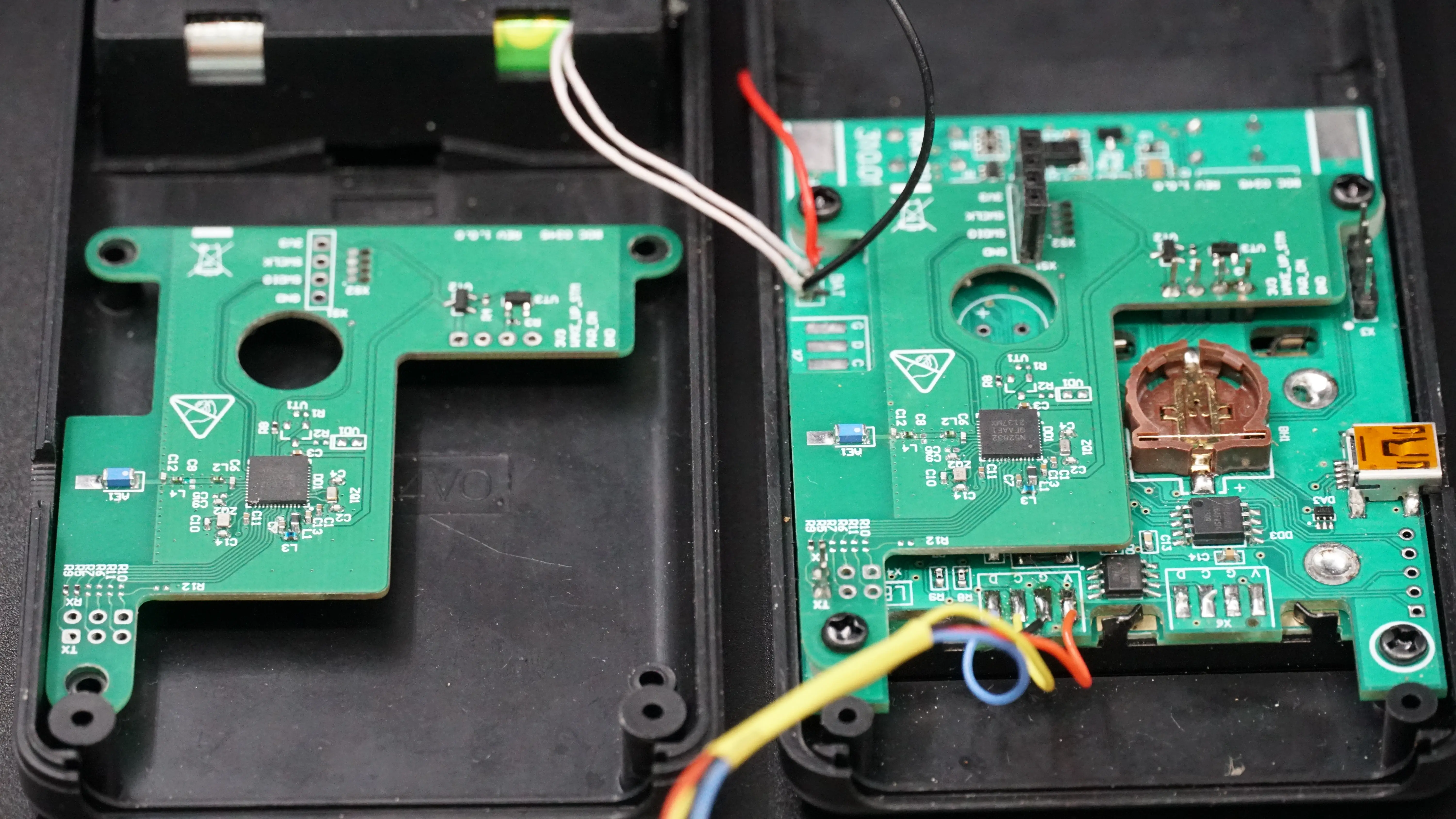
BLE receiver shield installed inside the existing data processing unit
This architecture meant that previously manufactured instruments could be upgraded without replacing their main electronics. It also made the wireless functionality optional. The client could add the BLE shield only to instruments that needed wireless probes, leaving other units in their original configuration.
Developing a Universal Wireless Probe Module
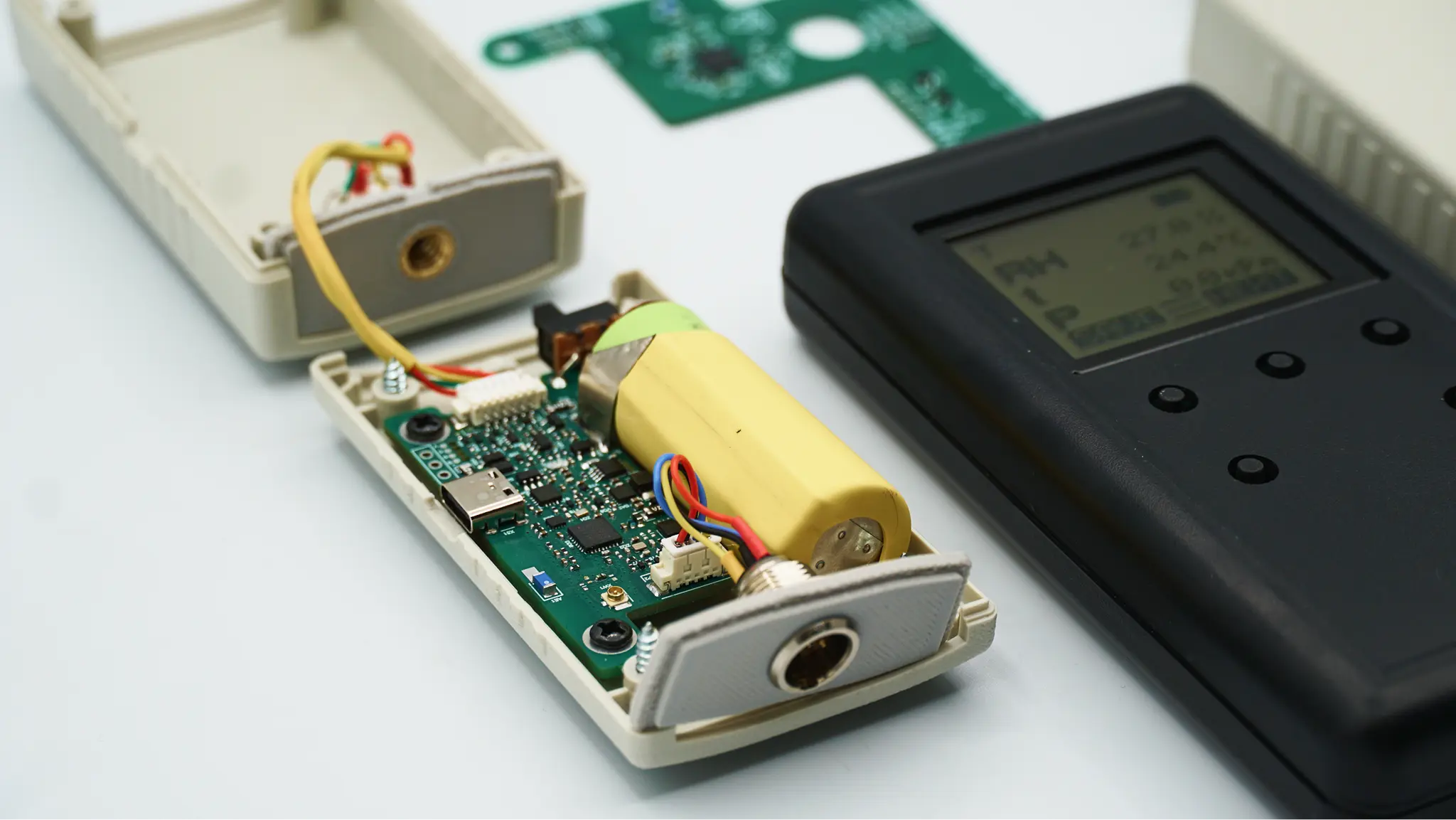
In addition to the receiving BLE shield, we developed a separate portable module from scratch to connect the client's existing measurement probes.
Instead of creating a dedicated wireless version of each sensor, we designed a universal electronic module that could work with any one of the supported probes.
Wireless measurement module with an attached sensor probe
The module read data from the connected sensor, formatted it into a predefined data packet, and transmitted it to the data processing unit over Bluetooth Low Energy. It did not perform complex mathematical calculations. Its role was to acquire reliable measurements, package them correctly, and deliver them to the central instrument.
This approach allowed the client to reuse existing measurement probes without redesigning their sensing elements. The main changes involved the supporting electronics: power supply, data acquisition, and wireless transmission.
On the receiving side, the BLE shield decoded incoming packets and passed the readings to the existing firmware. The data source remained transparent to the measurement algorithms: readings could arrive over a wired connection or Bluetooth, but they were then processed in the same format using the original logic.
To avoid rewriting the main instrument's processing logic, as required by the client, we introduced an intermediate data-source selection layer in its firmware. The system first checked whether a sensor was physically connected, then looked for the corresponding wireless data. If both sources were available, the firmware followed a predefined priority.
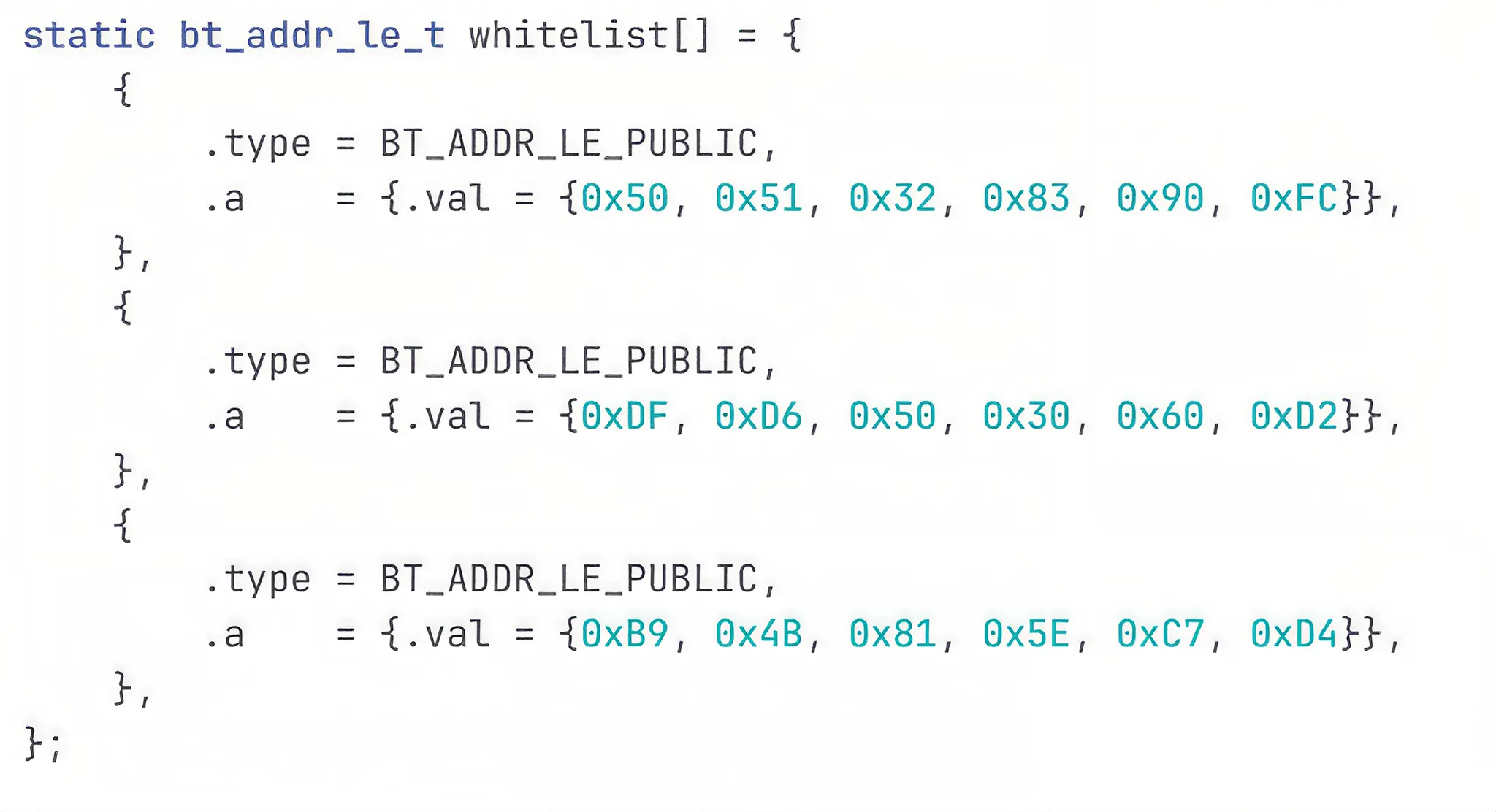
In the prototype, wireless modules were associated with a specific data processing unit using MAC addresses hardcoded into the firmware. This provided a straightforward way to establish a controlled working system while preventing unintended connections to other nearby devices.
Hardcoded BLE device whitelist used in the prototype firmware
However, this approach had a limitation. If a probe module needed to be replaced, its new MAC address would have to be added to the firmware, and the instrument would need to be reprogrammed. This was acceptable for the pilot batch, but a production version could benefit from a more convenient pairing procedure through the instrument's interface or a dedicated mobile application.
PCB Design and Component Layout
The compact wireless module had to accommodate a microcontroller, BLE antenna, rechargeable battery, charging circuitry, power management circuits, an external sensor interface, a push button, status indicators, and programming connections.
Prototype PCB and rechargeable battery inside the compact wireless module
We started with the overall physical layout. Our engineer selected a suitable enclosure, prepared a 3D model, and arranged the main components inside it. Once the client approved the external design, the available internal space became one of the key constraints for PCB development.
Miniaturization was not an explicit requirement in the technical specification. However, we benchmarked the design against comparable commercial devices.
Even if the module met every functional requirement, a device twice the size of existing market alternatives would be less competitive. At the same time, reducing the size indefinitely was not practical.
The project involved a small production batch with predominantly manual assembly rather than a fully automated manufacturing line. We therefore had to balance enclosure dimensions, functionality, and manufacturability.
As the circuit design progressed, we found that some standard components would not fit within the available PCB area. In particular, we had to replace transistors in the originally selected packages with smaller alternatives.
All prototype boards were successfully assembled, but this decision revealed a manufacturing constraint. Although the smaller components met the electrical requirements, they made assembly considerably more difficult. If the client decides to move to mass production, the transistor selection will need to be reconsidered. Possible solutions include choosing components compatible with a standardized assembly process or outsourcing assembly to a manufacturer with automated production equipment.
Battery and Power Management Design
Long battery life was one of the key requirements for the wireless module. The device needed to remain operational throughout extended measurement sessions rather than require recharging after a single day of use.
We based the battery subsystem on solutions already proven in our previous projects. This allowed us to reuse a validated approach to charging and battery monitoring instead of developing the entire architecture from scratch.
The module included controlled battery charging, battery voltage monitoring, and a dedicated fuel gauge. The fuel gauge could continue tracking the battery's state independently of the main microcontroller, even while the controller was in deep sleep.
Controlled battery charging, battery voltage monitoring, and a fuel gauge
This was important because measuring battery voltage alone does not provide an accurate indication of the remaining charge under all operating conditions. The dedicated fuel gauge provided more informative battery-state data, which the main controller could retrieve after waking up.
We also implemented power control for the external measurement probe. Since readings were taken at defined intervals, the sensor did not need to remain powered continuously. Instead, the firmware enabled the sensor's power supply immediately before taking a measurement and switched it off once the data had been collected.
A complete shutdown is not always the most energy-efficient option. For some components, restarting from a fully powered-down state takes more time and energy than remaining in deep sleep. We selected operating modes based on the characteristics of each subsystem rather than applying the same power-saving strategy throughout the device.
Special attention was given to the power button. In a conventional implementation, the microcontroller would need to continuously monitor the button's state, consuming power even when the device was otherwise idle.
Our design used a hardware wake-up circuit instead. In sleep mode, only a minimal, ultra-low-power part of the circuitry remained active. Pressing the button triggered the power-up sequence and started the main controller without requiring continuous firmware polling.
The status LEDs were activated only after the device woke up. The board supported RGB indication, allowing the firmware to use different colors to communicate operating states, errors, connection status, and battery charging.
Power Consumption Optimization
We evaluated power consumption not only through component datasheets but also through measurements on the assembled hardware.
A dedicated power profiler was connected between the power source and the PCB. It captured both sleep-mode consumption and short current spikes during sensor activation, microcontroller operation, and BLE packet transmission.
The resulting current profile helped our engineers identify which subsystem was waking up, how long it remained active, and how quickly the device returned to its lowest-power state.
Power optimization was carried out at both hardware and firmware levels. The PCB design allowed individual functional blocks to be powered down, while the firmware controlled sensor polling intervals, startup delays, and peripheral operating times.
For example, if a sensor required several milliseconds to become operational, the firmware would enable its power supply, wait for the necessary interval, take the measurement, and immediately switch it off. Unused peripherals were not left running between measurements.
BLE transmission required separate optimization. Average power consumption depended on radio transmit power, packet frequency, and the number of repeated transmissions. When the devices were close together and the connection was stable, fewer transmissions were needed. At longer distances, improving communication reliability required additional energy.
Status indication also accounted for a noticeable share of the power budget. Although an LED consumes relatively little power at any given moment, it needs to flash regularly and remain bright enough for the operator to notice.
We could not eliminate visual indication altogether, as users needed a simple way to confirm that a probe installed somewhere in the room was still operating. The final indication behavior therefore balanced flash frequency, brightness, and battery life.
Protecting the Sensor Interface
In the original instrument, external probes were connected almost directly to the main electronics. A damaged cable, short circuit, or incorrect connection could potentially damage the main processor.
For the new portable module, we decided not to repeat this architecture. The device would be used by operators under real working conditions, where incorrect connections and faulty external equipment could not be ruled out.
We introduced galvanic isolation between the I²C sensor interface and the main PCB circuitry. The external probe's power supply was also routed through dedicated control and protection circuits.
As a result, faults caused by shorted contacts, incorrectly connected connectors, or damaged sensors would not propagate to the microcontroller and disable the entire wireless module.
The new electronics therefore did more than introduce BLE connectivity. They also provided a protective barrier between the measurement probe and the module's main circuitry.
Firmware Programming and Debugging Interfaces
When designing the PCB, we anticipated that the module would need repeated firmware updates and testing long before the final product configuration was ready.
If we had included only the interfaces explicitly required for normal operation, debugging would have involved temporary wires, soldered connections, or a separate programmer. This would have complicated development and increased the risk of damaging prototype boards.
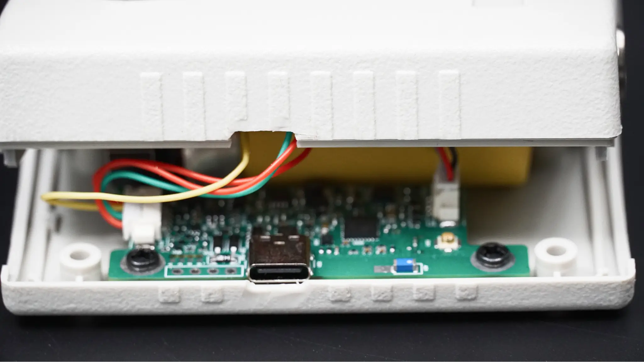
To avoid these issues, we added a USB-C connector and a local service interface for firmware programming, diagnostic output, and monitoring raw sensor readings.
USB-C service interface for firmware programming and sensor diagnostics
Close-up of the wireless module PCB inside an open white enclosure, showing internal wiring and a centrally located USB-C connector
This allowed us to test the electronics independently of the main processing unit. An engineer could connect the module to a computer and immediately check whether the sensor was responding, the power system was operating correctly, and the data was being prepared for BLE transmission in the expected format.
The same interface remained useful during later project stages. It was used for firmware updates and software debugging, reducing the time needed for integration.
USB-C also provided a starting point for future product development. At the hardware level, the module could already be connected directly to a computer or mobile device without using the main processing unit as an intermediary.
Development interfaces should be considered early, not added as an afterthought. The dedicated UART/USB-C service interface simplified local sensor diagnostics and supported faster integration. It also created opportunities for future versions in which measurements could be collected or verified without the central processing unit.
Recovering and Updating the Main Unit Firmware
Before introducing BLE connectivity, we first had to get the original processing unit's firmware working reliably.
Our engineers restored the firmware build, resolved critical issues, and brought the instrument back to a working state in its original wired configuration. Only then could we properly verify that wireless integration did not interfere with existing functionality.
The measurement algorithms themselves were left unchanged. The client explicitly required the mathematical processing routines to remain intact, so we focused on data integration rather than expanding the scope into a redesign of the measurement logic.
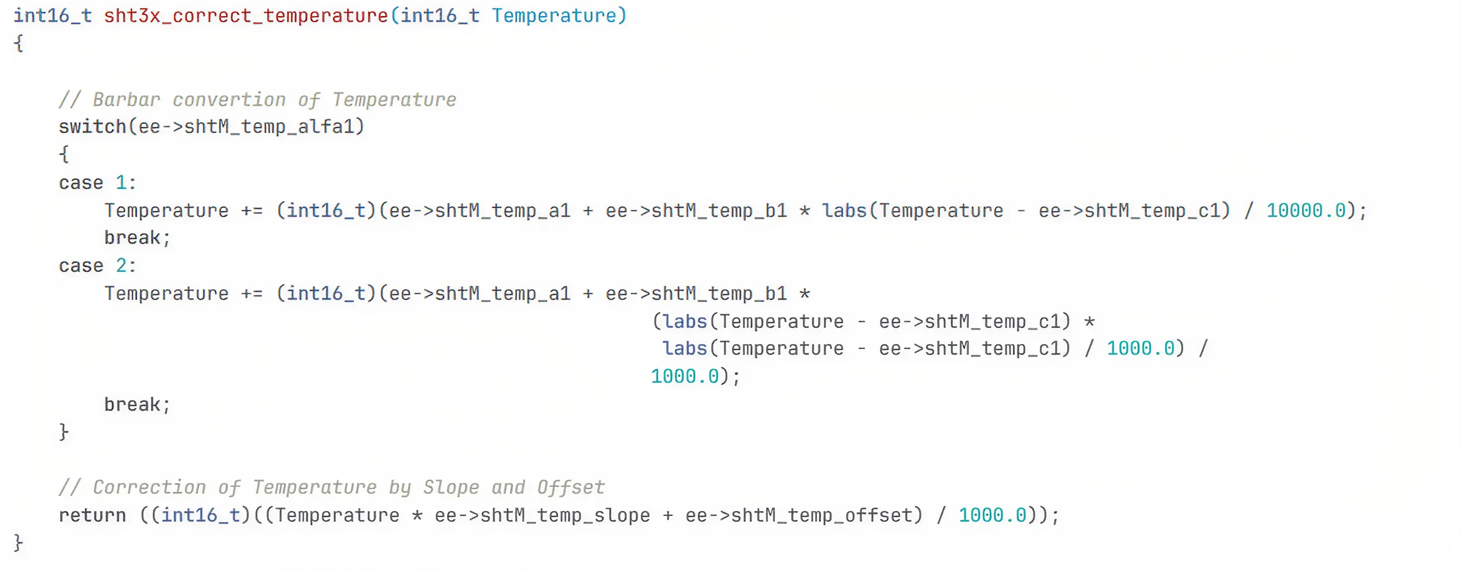
The original firmware already included measurement filtering. This filtering smoothed natural fluctuations in sensor readings and prevented the least significant digits on the display from changing continuously under essentially stable conditions.
Temperature processing logic in the main unit's embedded firmware
After moving the instrument, readings needed some time to settle. This behavior was expected for equipment of this type, so we retained the existing processing algorithms and focused on ensuring that the new data was transmitted correctly.
We then added BLE shield communication and data-source selection logic to the firmware. Wireless readings could now enter the same software routines previously used for wired sensor measurements.
Integrating the Measurement Probes
At the start of development, the client could provide only two of the three supported probe types.
Rather than put the project on hold, we developed the hardware and firmware integration around the sensors already available. Their interfaces were sufficiently similar to allow much of the integration work to proceed without a physical sample of the third probe.
The missing sensor arrived several months later. During testing, our engineers found that its readings did not match the expected values. We initially investigated the new PCB, data format, and firmware integration, but eventually traced the problem to the probe itself.
Waiting for a complete sensor redesign would have delayed the entire project. Together with the client, we agreed on a minimum verification scope: the wireless module had to demonstrate communication with the probe and successfully retrieve at least one measurement value. Once this was confirmed, the sensor was returned for further development, while our team continued with the remaining work.
This approach validated the communication interface without redesigning the client's sensor hardware.
Redesigning the User Interface
The main unit's user interface required a complete rewrite.
The client supplied a new visual framework and the main screen layouts. We adapted these materials to the dimensions, resolution, and technical limitations of the actual display.
The original designs could not simply be transferred into firmware without modification. During implementation, we adjusted element dimensions, label positioning, and screen behavior. Some graphical elements required almost pixel-by-pixel preparation and alignment.
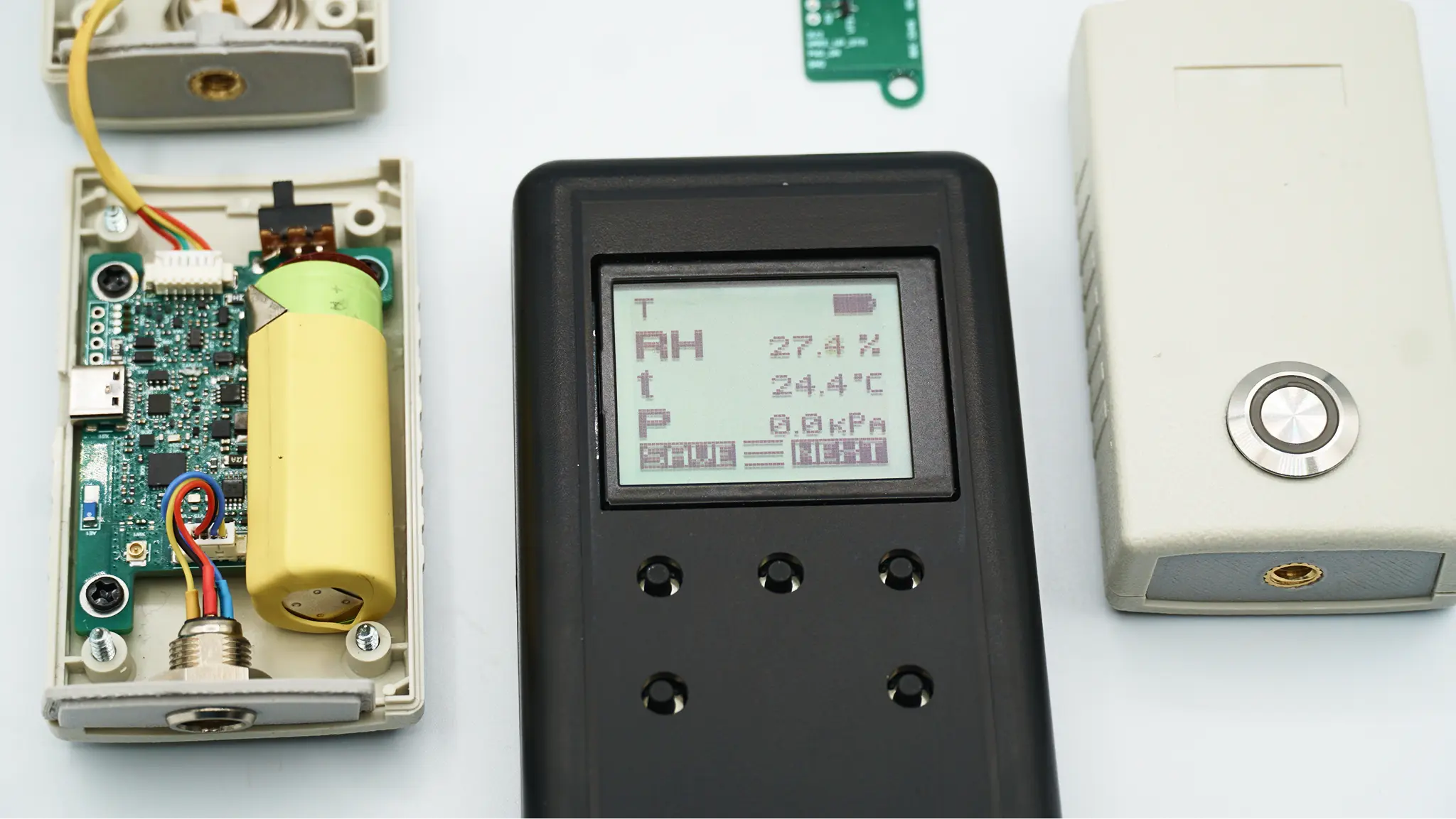
The updated interface needed to show more than measurement values. Operators also needed to know which probe was selected, whether data was being received, and whether the wireless connection had been lost.
Updated climate meter interface displaying environmental measurements
During normal operation, the probe transmitted a message approximately once per second. If the main unit received no data for five seconds, the firmware treated the probe as disconnected and updated its status on the screen.
Enclosure Design and Manufacturing Preparation
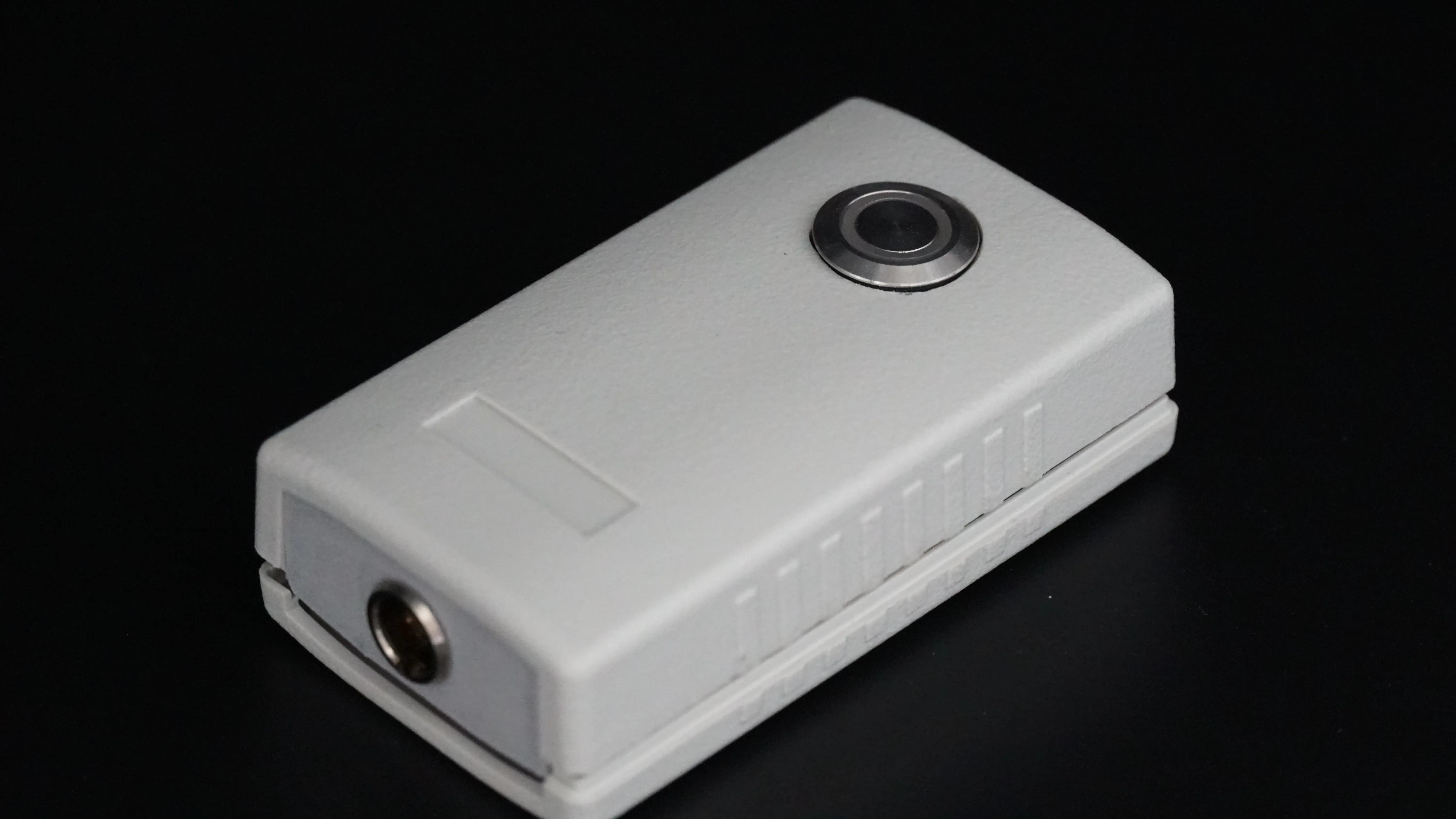
We used a compact off-the-shelf enclosure for the wireless module, but it still required mechanical modifications to accommodate the final design.
Compact enclosure selected for the wireless measurement module
Our engineer developed a 3D layout, positioned the PCB and battery, and defined the locations of connectors, the button, and status indicators. After the enclosure design was approved by the client, the PCB outline was finalized around its available internal volume.
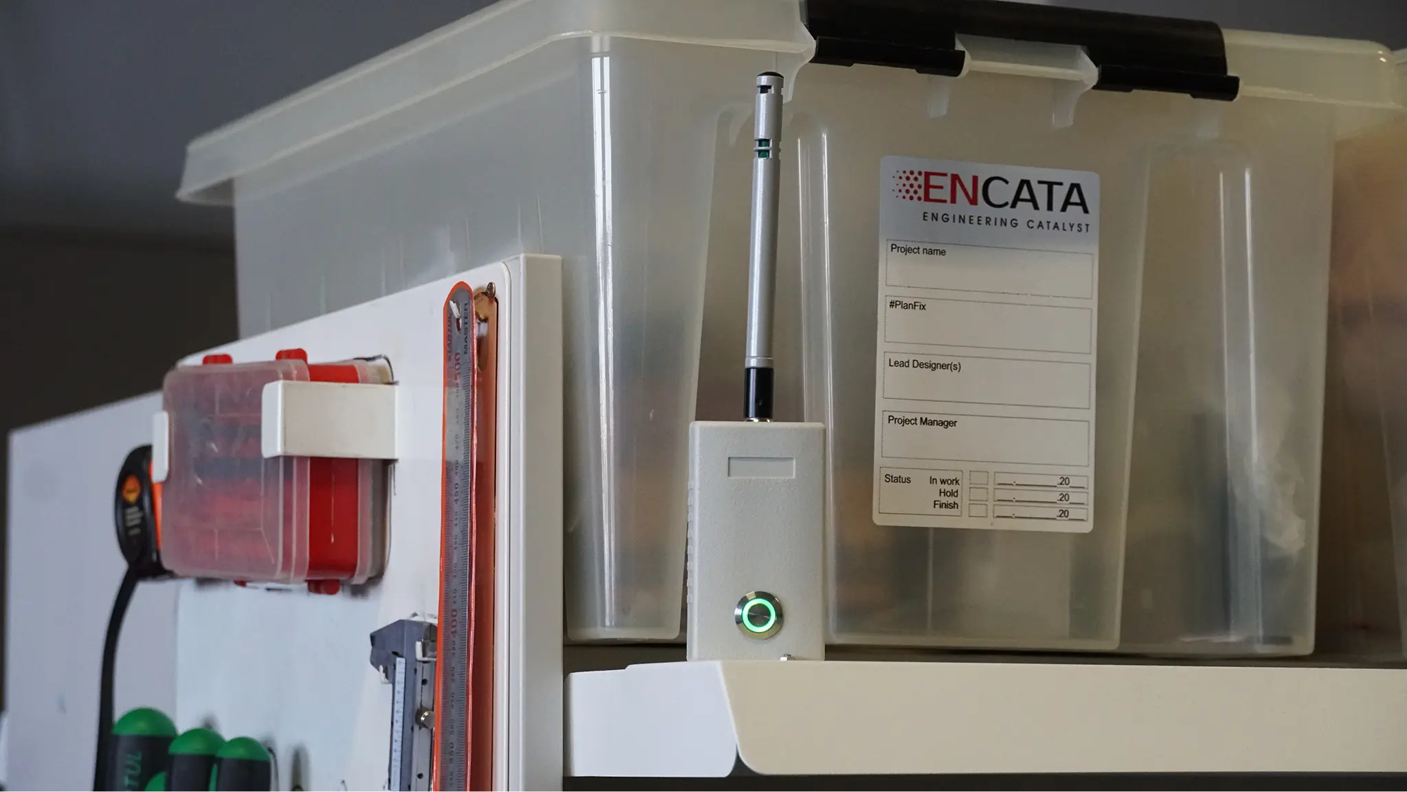
The enclosure was also modified for tripod mounting. We added a heat-set threaded insert to provide secure attachment and allow the probe to be positioned at the required measurement point inside a room.
Finally, we brought the enclosure, PCB, battery, fasteners, and other components together into a unified design and manufacturing documentation package. This gave the client a complete product assembly rather than a collection of unrelated parts, providing a practical basis for the next stage of manufacturing preparation.
Results and Benefits
The client received a working set of wireless digital probe prototypes for an indoor microclimate meter. The probes can transmit measurement data to the existing processing unit over a wireless connection, while the redesigned user interface makes the instrument easier to operate and supports new measurement modes.
The project also provided the client with the engineering documentation and embedded firmware needed to further develop the wireless probe architecture. The solution creates a foundation for a more flexible product range, allowing probes to be positioned throughout indoor spaces while the main unit collects readings without a direct wired connection to each measurement point.
50 units
upgradeable MPU boards
3 units
wireless probe module prototypes
10 m
stable BLE range
Our Role
Requirements analysis
Electronics engineering
Firmware development
Mechanical engineering
Pilot batch manufacturing
Design and manufacturing documentation
Explore Similar Cases
Custom Thermal Manikin Testing System
EnCata developed a thermal manikin testing system to evaluate fire-protective clothing. The system features high-efficiency thermal panels, a mobile manikin with 180° rotation, and a crane-beam mechanism adapted to the facility’s space and ventilation layout.
EnCata engineered a custom tire pressure sensor (TPMS) test stand for industrial QA—developing mechanics, electronics, and firmware from scratch. The compact device supports 10 chambers. All IP belongs to the customer.