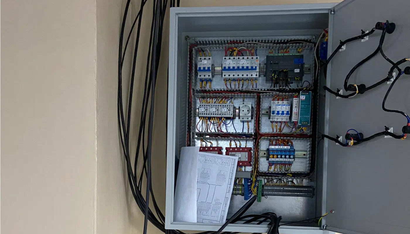
EnCata developed a control cabinet that manages a heat chamber (60 °C heating, humidity, ventilation, safety) and integrates a cold chamber and chiller via RS-485 for one of its customers. The cabinet is part of a climate system designed for simulating extreme temperatures for firefighters.
The engineering team encountered several key difficulties throughout the project:
Recovering the RS-485 protocol of an off-the-shelf cold chamber. The cold chamber came from a third-party manufacturer, and the RS-485 interface documentation supplied with it was incomplete: some commands returned errors, others returned data in different registers than the documentation described. The supplier's support team could not resolve it. We still needed to bring the chamber's readings into the shared operator workstation.
A high-power heating circuit with two independent requirements. The heat chamber is designed to test a person in protective gear, so its heating circuit had to meet two separate requirements at the same time. First, hold temperature to ±2 °C under heavy load: for a PID controller this means switching the heater frequently, and ordinary electromechanical switching would wear out quickly at that rate. Second, shut the heaters down reliably if heating ran away due to a firmware fault. Software alone could not be the only safeguard, so we needed a separate hardware circuit independent of the PLC.
Bringing data from different subsystems into one electronic test record. The cabinet became the point where all the data converged — streams of different kinds, from different manufacturers: wireless sensors on the test subject, heat- and cold-chamber readings over RS-485, IP video, and two-way operator–subject audio. All of it had to land in a single electronic test protocol with a unified time base, key events logged automatically and a final report in the customer's format. The challenge was not any one interface, but combining them all into a single record.
Challenges
01
Recovering the RS-485 protocol of an off-the-shelf cold chamber.
The cold chamber came from a third-party manufacturer, and the RS-485 interface documentation supplied with it was incomplete: some commands returned errors, others returned data in different registers than the documentation described. The supplier's support team could not resolve it. We still needed to bring the chamber's readings into the shared operator workstation.
02
A high-power heating circuit with two independent requirements.
The heat chamber is designed to test a person in protective gear, so its heating circuit had to meet two separate requirements at the same time. First, hold temperature to ±2 °C under heavy load: for a PID controller this means switching the heater frequently, and ordinary electromechanical switching would wear out quickly at that rate. Second, shut the heaters down reliably if heating ran away due to a firmware fault. Software alone could not be the only safeguard, so we needed a separate hardware circuit independent of the PLC.
03
Bringing data from different subsystems into one electronic test record.
The cabinet became the point where all the data converged — streams of different kinds, from different manufacturers: wireless sensors on the test subject, heat- and cold-chamber readings over RS-485, IP video, and two-way operator–subject audio. All of it had to land in a single electronic test protocol with a unified time base, key events logged automatically and a final report in the customer's format. The challenge was not any one interface, but combining them all into a single record.
Approach & Solution
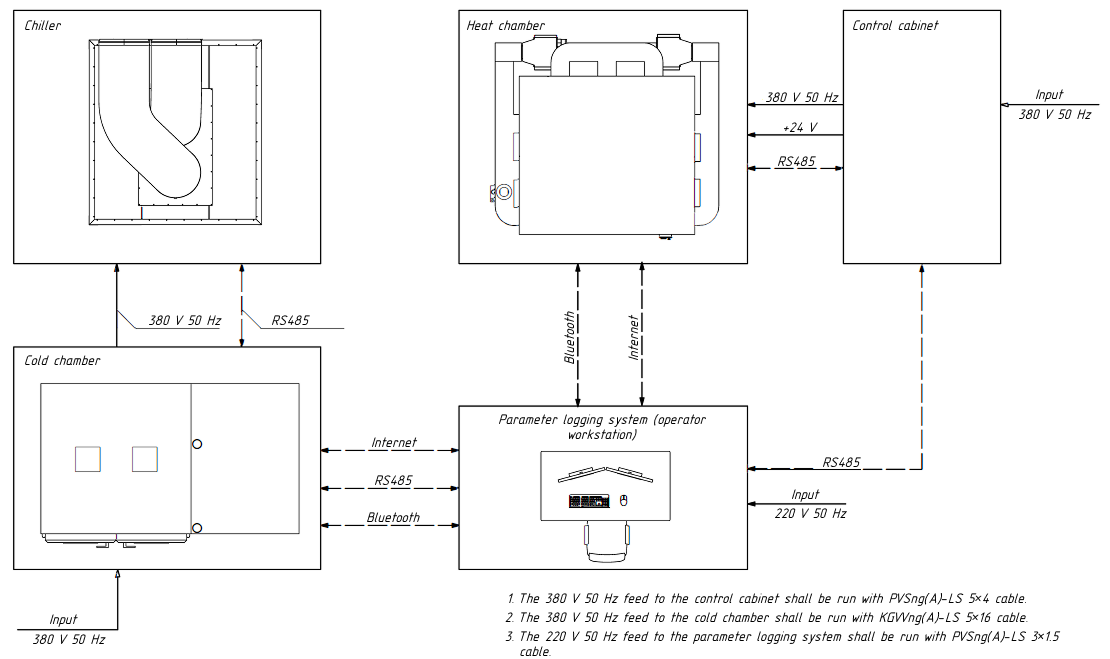
The automation cabinet was a core part of the climatic test setup from the start – the unit that ties the heat chamber (and its humidifier), the cold chamber, ventilation, and the safety elements into one loop. We therefore approached it from the outset as building an automated process control system (APCS), not simply selecting a controller to heat the chamber, even though much of the logic we wrote came down to exactly that.
System architecture diagram
Beyond coordinating the interaction between system components, the control cabinet had to:
keep an electronic test protocol, recording test parameters and modes;
log the test start time in the electronic test journal as soon as the operator signals the start;
collect readings from the sensors tracking the target parameters and write them to the protocol;
notify the operator when a test finishes;
alert the operator when a tracked parameter goes out of range, and log that event;
let the operator add notes about the test and save them with the record;
provide one-way video (the operator can see the subject in the chamber) and two-way audio (the operator can speak to the subject and hear them);
show the operator the test's progress in real time.
We implemented all of these functions, as described below.
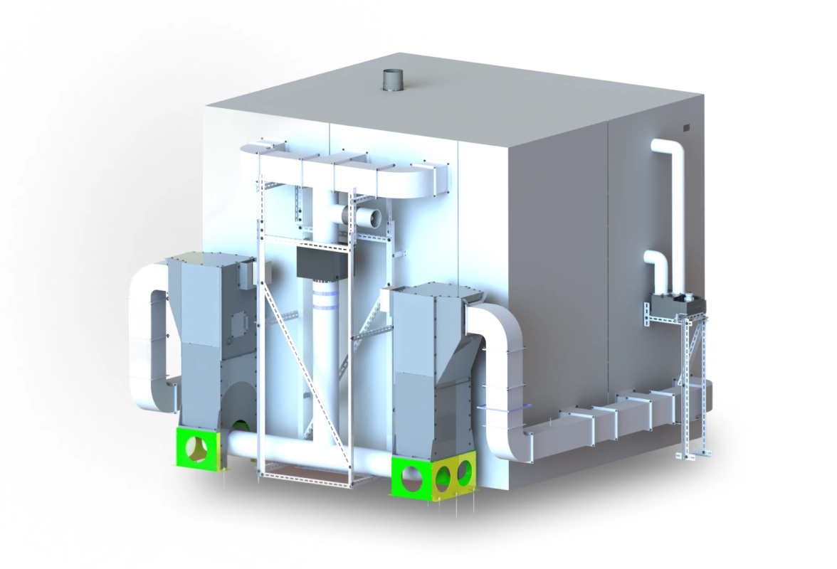
Heat chamber layout and power sizing
Heat chamber model
We defined the heat chamber layout in parallel with the cabinet itself. Thermal calculations and simulation set the system's main power figures: 6 kW of heating in total, split across two sections of three 1 kW tubular heaters each, plus two fans in the supply-and-exhaust system driven by single-phase motors rated up to 300 W (supply and circulation). These heaters and fans define the cabinet's main power components – heaters, motors, humidifier – and the electrical side is selected around them: switching, controller, protection circuits, measurement channels. Working in this order let us settle the mechanical and electronics requirements into one agreed parts list before purchasing anything for the cabinet.
Choosing a PLC over a PID controller
We considered a PLC rather than PID controllers from the start, since a PID controller would only hold one temperature on the heating loop. The control scheme also grew as the project went on: humidifier control, two independent fans (fresh air and moisture), a safety loop, and integration with the off-the-shelf cold chamber, with its readings shown at the operator station. Given all of that, running the architecture through a PLC was the only reasonable choice. The PLC takes in every measurement signal, runs PID control of the heating, humidifier, and fans, and communicates with the cold chamber and chiller over Modbus RTU on RS-485.
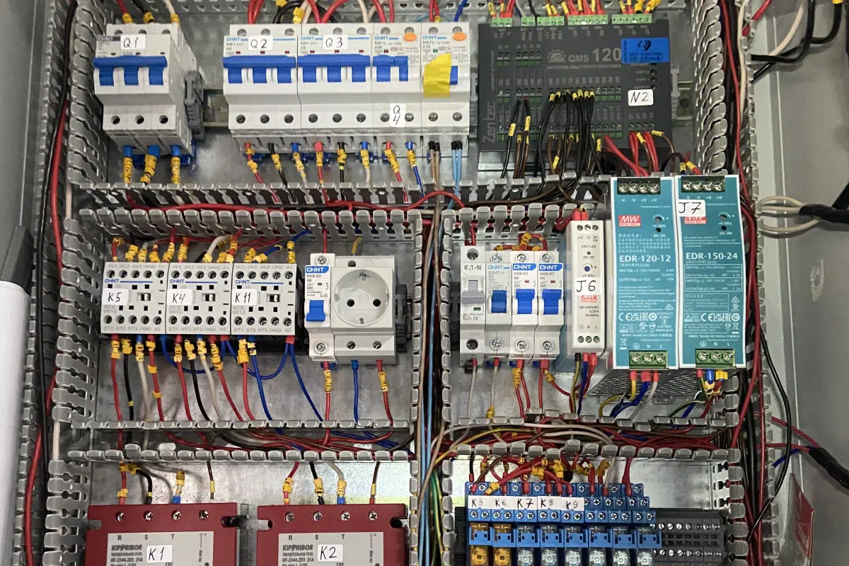
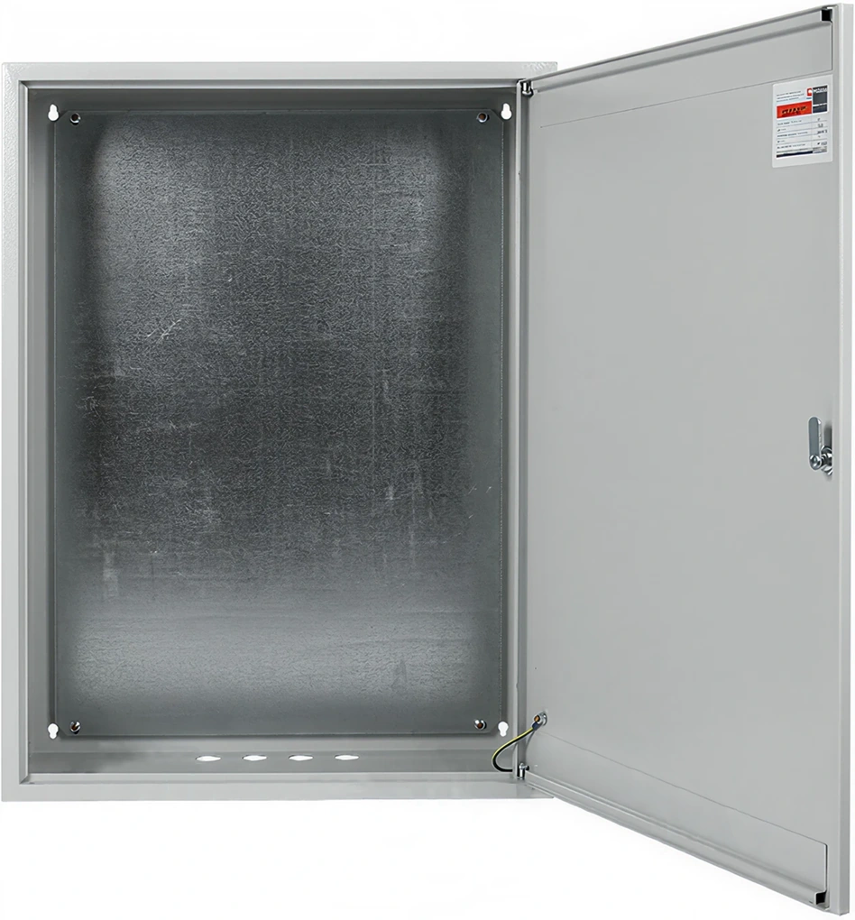
Enclosure and internal layout
An off-the-shelf enclosure
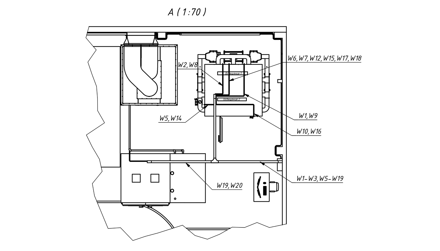
We selected the cabinet enclosure from off-the-shelf distribution panels, working from a preliminary component layout (part of the structural diagram is shown below).
Part of the preliminary component layout scheme of the automation cabinet
This approach kept costs down for the customer without hurting system performance, avoiding issues such as insufficient ventilation space or components mounted too close together. A standard enclosure was sufficient; the only addition our team had to make was holes for the system status indicator, which we drilled ourselves.
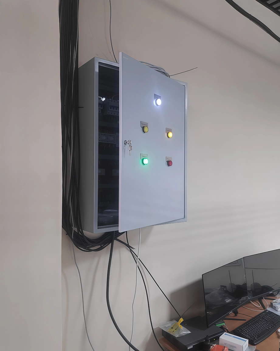
Automation cabinet system status indicators
We did the internal layout in AutoCAD: components placed at true scale on DIN rails, cables run in perforated trunking, and power and signal brought in through separate terminal groups.
Working with the PLC
The PLC became an engineering challenge of its own. We had worked with this manufacturer's components before with good results. This time, however, the controller did not behave as its documentation stated in a few basic areas: the actual timing intervals did not match those we set, and the same program ran differently in debug mode (streaming data to the PC) and after release (without it). The manufacturer was slow to respond, so we corrected it ourselves. To get the system stable, we verified every critical function with physical measurements, calibrated the key timers empirically, and re-checked the release-mode behavior separately before handover. We brought the controller to reliable operation within the system.
It is worth noting that we stayed on schedule and within budget. We chose to continue with this PLC because we knew our expertise was enough to finish on time, and the experience was a useful reminder that even a proven brand's components can fail.
Cold chamber integration
In parallel, we worked on integrating the off-the-shelf cold chamber into the system. Its manufacturer did not provide complete RS-485 documentation: some commands returned errors, others returned data in the wrong registers. Going through the supplier produced no result, so we recovered the protocol by reading the bus directly and built a working polling scheme from the commands we found. We also added LED luminaires inside the chamber, since the stock incandescent lamps did not meet the illuminance the specification called for. We ran the luminaires at 24 V to ensure the necessary level of safety.
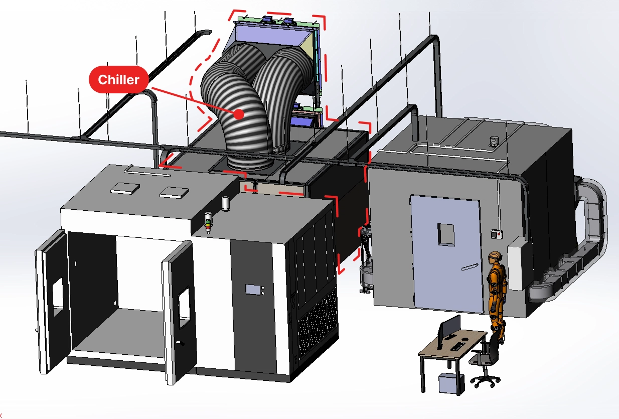
Climate test system layout with chiller
We left the chiller as a standalone unit: it holds the coolant temperature on its own using its loop and flow sensors, and only takes power from the cabinet.
A unified electronic test protocol at the operator workstation
To combine data from these different subsystems into one record, we set up three parallel acquisition channels at the operator station. Heat- and cold-chamber readings come from the cabinet PLC to the PC through a USB↔RS-485 converter over Modbus RTU. The Blue PUCK T-PROBE wireless temperature loggers (15 units) and a Garmin HRM-Pro Plus heart-rate monitor connect to the PC directly over BLE; for these, we wrote a routine to identify each sensor and tie it to a zone on the subject's body (a manikin diagram in the software). Video runs through a separate application, IVMS-4200, which writes files on the same timestamps as the main protocol. In our software, everything lands in one record on a shared clock: test start and end, out-of-range events, and operator notes log automatically; temperature and heart-rate graphs draw in real time; and when the test ends, the report comes out in the customer's standard format.
A software loop can't be the only safety layer. A climatic chamber for human testing needs a hardware safety circuit independent of the PLC
On-site commissioning
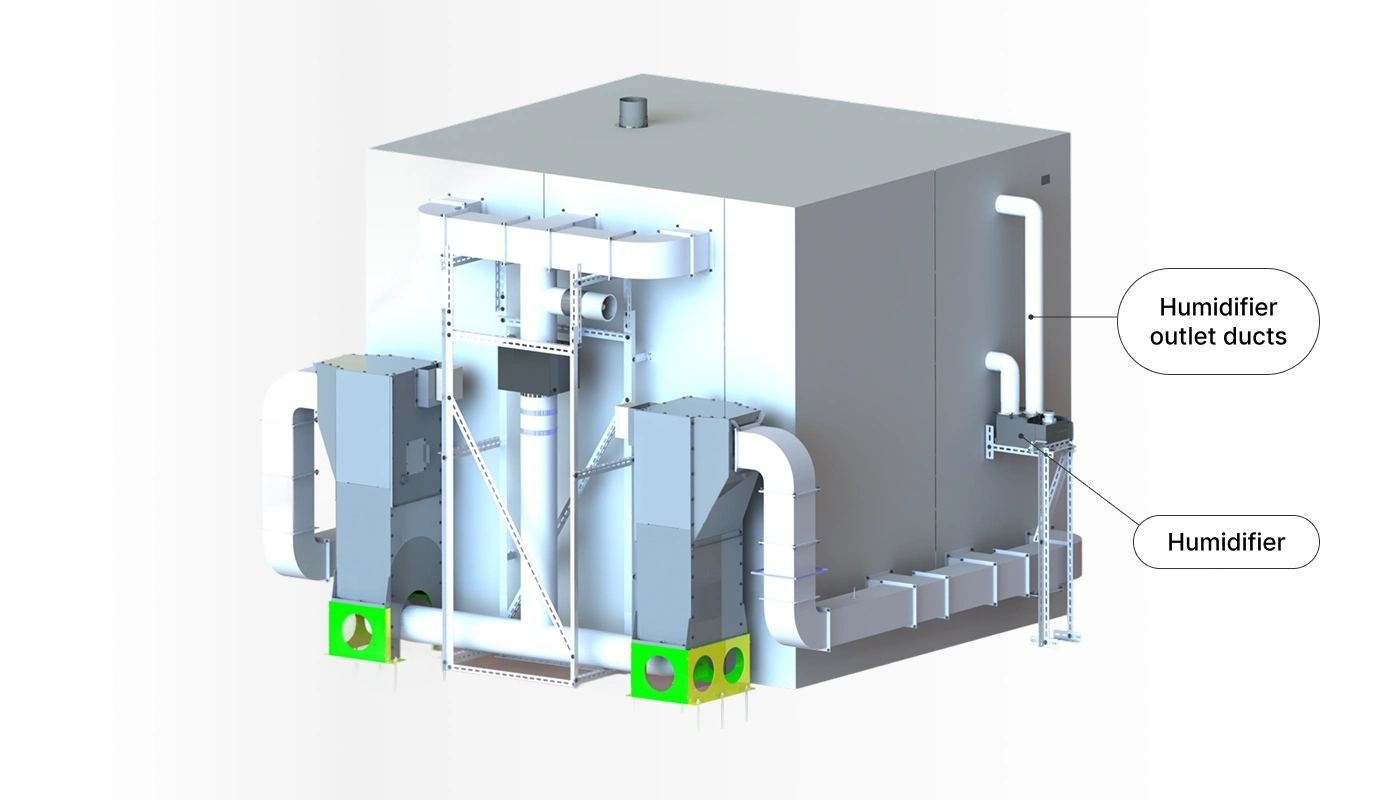
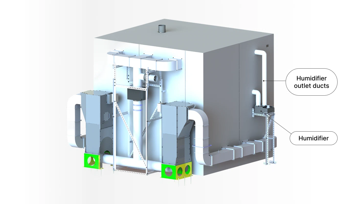
The final stage was commissioning at the customer's site. The first tests revealed one functional problem with the heat chamber that affected the cabinet logic: the humidifier, originally placed in one of the heating-tube wings, was not delivering humidified air into the working volume: the steam was condensing partway through the ducts.
We resolved it as follows: we separated the humidifier from the main heating duct and made it standalone, with its own piping and fan. To drive that fan, we reworked the cabinet, adding a dedicated power and switching line and updating the control program.
Solving the humidifier issue for a heat chamber
We also added a fresh-air channel to the main duct. After that, moisture supply settled into a stable regime. Following the same logic, we installed a separate inline fan ahead of the main loop to guarantee fresh air.
Results and Benefits
The project is complete. We designed and built an automation cabinet that controls all subsystems of the heat chamber – heating to ±2 °C, humidification, and ventilation – and maintains a hardware safety loop independent of the PLC. The readings from the off-the-shelf cold chamber and chiller are brought through the cabinet to a single operator workstation. At the customer's site, we carried out commissioning and trained the operators on the system.
The customer received:
a working automation cabinet (built on an off-the-shelf enclosure with a custom internal layout);
the electrical schematic and BOM;
PLC firmware (PID control of heating, humidifier and fan control, safety loop);
an operator workstation with HMI (Ethernet/Bluetooth/RS-485);
a set of operating documentation.
Important: EnCata does not sell the control cabinet. If you need a similar solution, write to us and attach your product requirements. We will get in touch and walk you through the specifics of development in your case.
6 kW
total power of the heating circuit
60 °C
upper temperature limit
8 hours
continuous operating time
Our Role
Concept development
Electronics engineering
Firmware development
Pilot batch manufacturing
Design and manufacturing documentation
Technical support
Explore Similar Cases
Custom Thermal Manikin Testing System
EnCata developed a thermal manikin testing system to evaluate fire-protective clothing. The system features high-efficiency thermal panels, a mobile manikin with 180° rotation, and a crane-beam mechanism adapted to the facility’s space and ventilation layout.
EnCata developed a heat chamber engineered to simulate extreme high-temperature environments. The unit heats up to 60°C with ±3°C uniformity across the full volume and features adjustable humidity control.