EnCata provided engineering services for a startup developing a custom soil testing rig with a stabilometer and load system. We delivered mechanical engineering, CAD, FEA, prototyping, and documentation. Built and tested from scratch in just 5 months.
Structural Reliability and Sealing Integrity: The stabilometer chamber is required to withstand pressures as high as 16 atm. At the same time, its dimensions must remain within a strict limit of 278×321 mm. Furthermore, the elevated pressure dramatically increases the risk of leakage, particularly at connection points.
Challenges
01
02
03
Approach & Solution
The customer approached us with a request to develop a triaxial compression testing rig for soil analysis. The project required the design of both a stabilometer chamber and a load application system. The goal was to deliver a solution that provided a competitive edge while meeting the international standard for such tests – ISO 3601-2. Additionally, the customer’s product team emphasized addressing user complaints about competitor solutions, particularly regarding the cumbersome and time-consuming process of loading soil samples. The presence of competitors also necessitated cost-efficient design and logistics to ensure the customer’s business model remained viable.
Stabilometer chamber diagram
Stabilometer Chamber Design
The stabilometer chamber comprises a base, body, rod, upper and lower punches, drainage and pressure system pipelines, and an indicator. A critical design requirement was selecting a transparent material for the body capable of withstanding pressures of up to 16 atm. To ensure durability, we conducted computational simulations to test material strength and determine the optimal placement of the fixation mechanism. Ultimately, we selected a mineral glass tube, which outperformed other materials, such as acrylic glass, in terms of strength.
In existing market solutions, the chamber body is typically secured using bolts that attach a metal lid (an approach that complicates usage, as filling the chamber with soil takes 4–5 minutes). We proposed an alternative locking method that eliminated the need for hand tools while preserving sealing reliability. After a series of simulations, we optimized the geometry and placement of the locking mechanism. As a result, we cut preparation time in half and removed the need for wrenches during setup.
A key design challenge was to ensure a reliable, cost-effective seal between the lower flange and the chamber base. We addressed this by developing and validating a sealing approach using an elastic element operating within a controlled gap. This solution ensures tightness under compression while avoiding the need for complex surface machining.
For the chamber’s moving component, we applied a sealing solution suitable for variable loads. We selected an element resistant to abrasion and capable of maintaining tightness under displacement.
Another key challenge was to ensure a reliable and stable connection for the latex tubing used to apply load to the soil sample. While rubber rings are commonly used in similar chambers, the client highlighted several shortcomings of such solutions in competitor products and provided specific requirements to ensure uniform contact between the plunger and tubing at the attachment point. To meet these requirements, we designed a spring-loaded clamping element with adjustable force. This solution prevents localized deformation and provides consistent, leak-free sealing under dynamic operating conditions.
Quick-release clamps for securing the latex tubing illustrated
The chamber also includes a dedicated sleeve for connecting a temperature sensor.
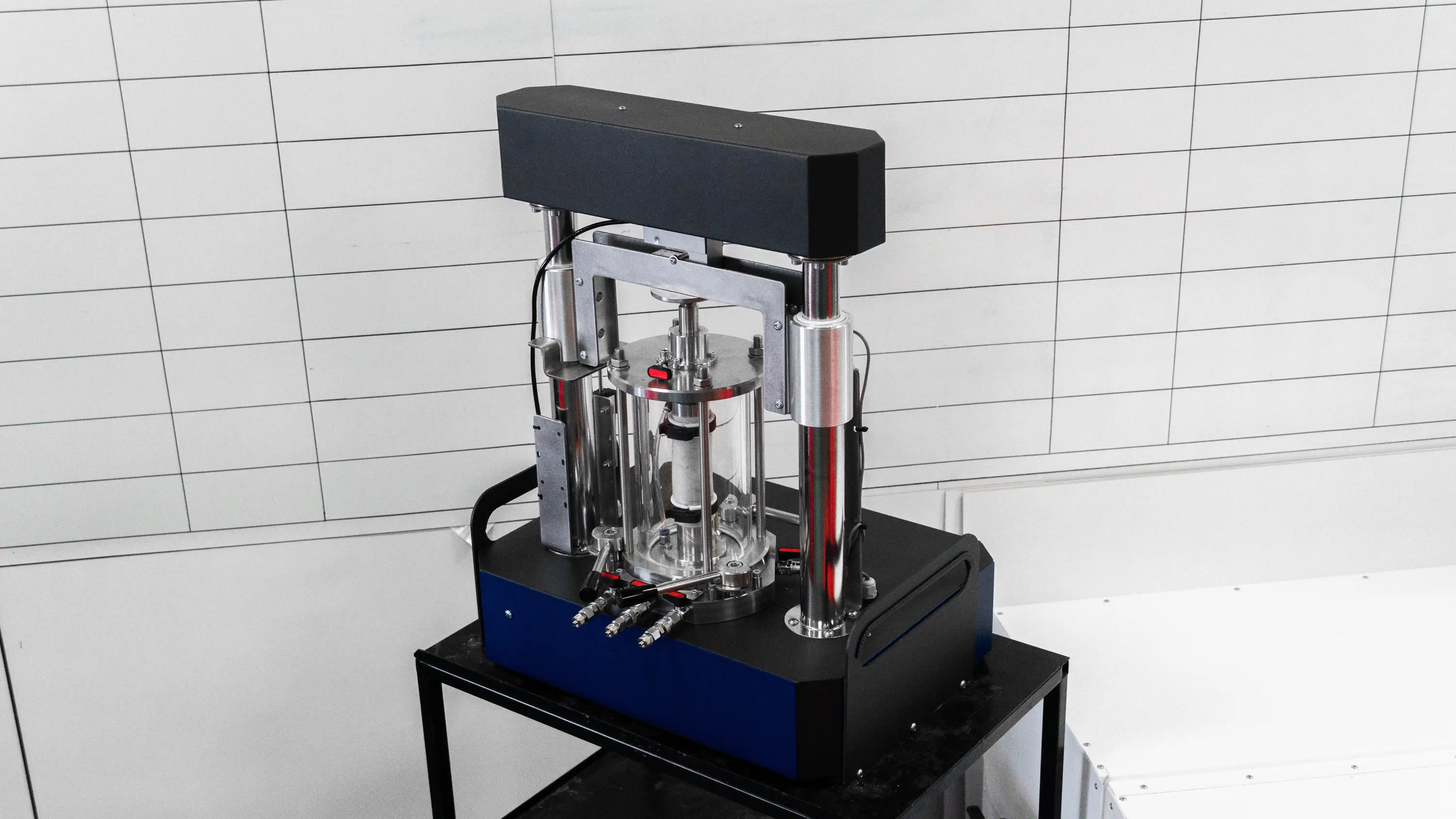
To validate our design, we produced a stabilometer chamber prototype, which met all functional and performance requirements.
Load Application System Design
As soon as we completed the design of the stabilometer chamber, we proceeded to design the electric drive-based load application system. The device consists of two parallel jacks with gear reducers, mounted on a shared crossbeam, which generate the loading force. Control of the force application is performed via a load cell. The load application system must accommodate a triaxial compression chamber with a maximum diameter of 200 mm and a height of 280 mm. The use of a stepper motor allows synchronizing the movement of the parallel actuators, which prevents skewing of the structure during loading.
Location of the stabilometer chamber illustrated
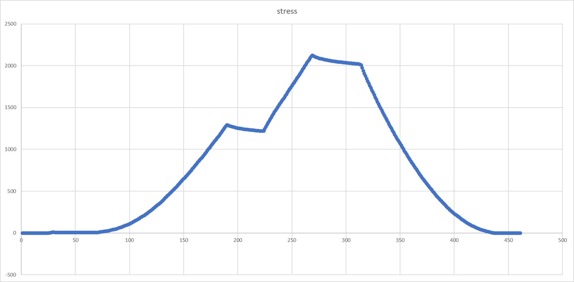
To verify the system's operability, we assembled a test bench and conducted load tests up to two tons. Force characteristics were monitored via a load cell, whose readings were acquired by an Arduino microcontroller using an analog signal digitization module. During the tests, the sensor was calibrated using reference weights to achieve the required measurement accuracy. The data was displayed digitally and additionally presented as a load-over-time graph.
Load-over-time graph
Initially, direct control of the stepper motor via Arduino was considered; however, we opted for a pulse generator during the testing phase. This choice ensured the stability and predictability of the system's operation under test conditions and allowed us to focus on verifying the mechanics and force characteristics.
The load application system is manufactured as a solid welded structure: after welding, we performed mechanical processing on a milling machine, ensuring precise dimensions. The jacks are trapezoidal with a total load capacity of 4 tons (2 tons per jack), which provides a reserve exceeding the Customer's requirements; this choice was agreed upon and fit within the budget, opening up possibilities for increased loads.
Results and Benefits
We delivered the manufactured stabilometer chamber and its load application system to the Customer. The test bench not only withstands pressures up to 16 atm but also facilitates quick and safe testing, proving to be an effective tool for soil analysis prior to foundation design.
EnCata developed a thermal manikin testing system to evaluate fire-protective clothing. The system features high-efficiency thermal panels, a mobile manikin with 180° rotation, and a crane-beam mechanism adapted to the facility’s space and ventilation layout.
EnCata developed a control cabinet that manages a heat chamber (60 °C heating, humidity, ventilation, safety) and integrates a cold chamber and chiller via RS-485 for one of its customers. The cabinet is part of a climate system designed for simulating extreme temperatures for firefighters.