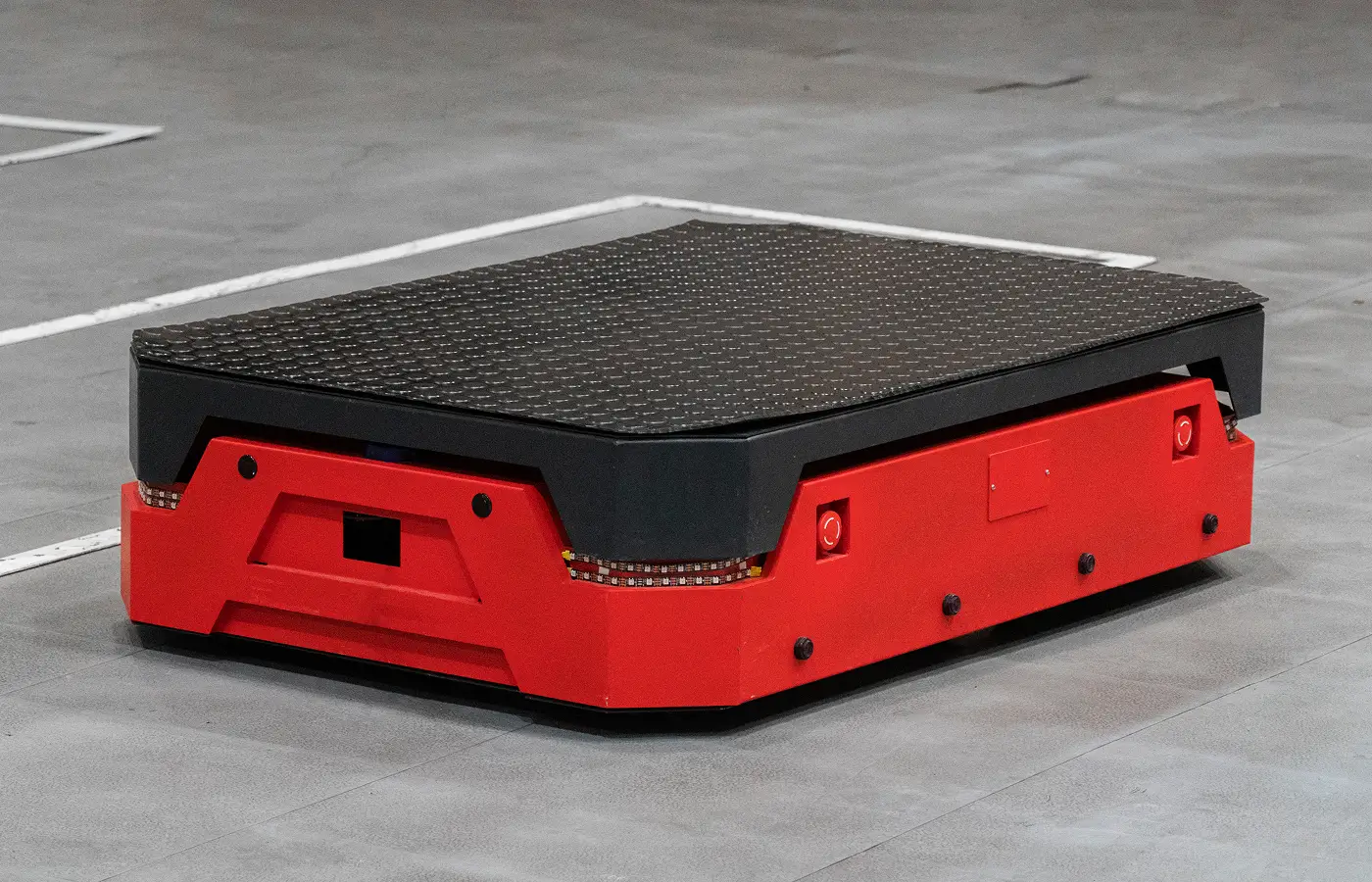
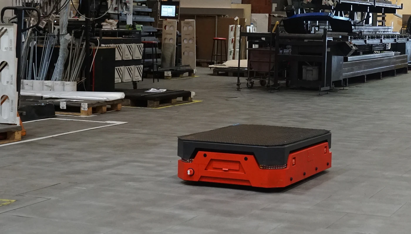
EnCata developed a minimum viable product – a robot for factory and warehouse automation. It can carry loads of up to 200 kg, operate autonomously for 3 hours without recharging, and features a 120×80×40 cm platform.
The robot was designed as an industrial automation solution. During development, our team encountered several key challenges in robot engineering, ranging from navigation in complex environments to safe power management and electronics unification.
Reliable navigation on ROS2. We knew the robot would operate in a real industrial environment with people, equipment, and dynamic obstacles. From the start it was clear that building stable navigation on ROS2 with mapping, localization, and collision avoidance would be a central challenge.
Safe power management. In robots powered by high-capacity batteries and motors, a critical challenge is to avoid arcing and overload during startup. We needed to design a soft-start scheme that would prevent battery protection from tripping and provide selective protection of different subsystems via fuses.
Electronics unification for four robot sides. Each side of the robot carried the same set of sensors and LED indicators. Normally this would require multiple PCB variants or separate firmware versions, complicating assembly and maintenance. We needed to design a universal board and firmware that could automatically recognize its position and role. This was not a trivial task, but it greatly simplified assembly, reduced firmware maintenance, and improved serviceability of the robot.
Challenges
01
02
03
Approach & Solution
A startup approached us to design a load-carrying robot for automating material handling in a production facility. The requirements were derived directly from the client’s manufacturing process.
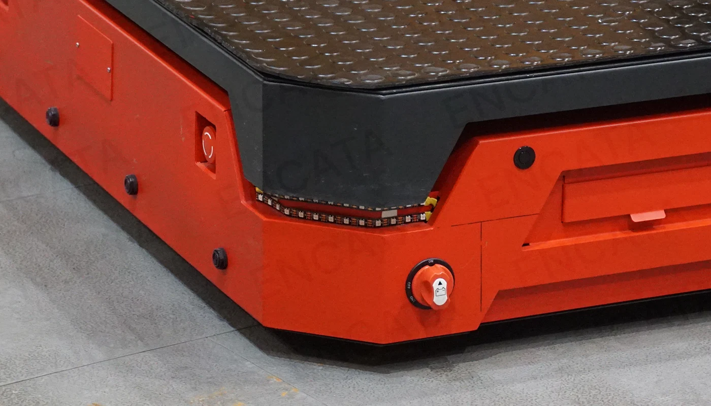
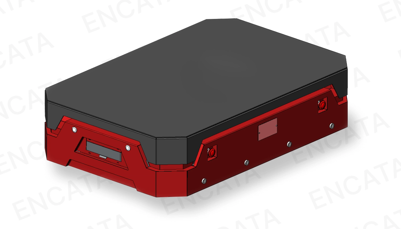
We developed an industrial design that went beyond aesthetics and shaped a functional enclosure directly affecting robot operation. We chose a bright red color for visibility in a busy workspace. Emergency stop buttons were recessed to avoid accidental triggering, while sensors and detectors were mounted on plastic covers, simplifying assembly and reducing weight.
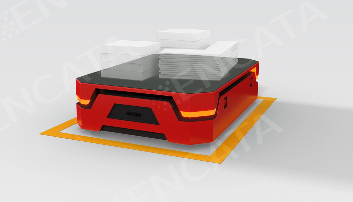
Industrial design of the warehouse robot
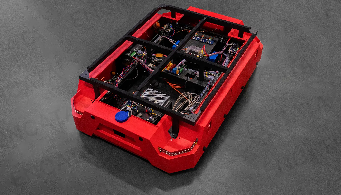
Our team applied mechanical engineering robotics expertise to design the structural frame. Load capacity, dimensions, and sensor placement had already been defined at the industrial design stage. For us, industrial design is not only about ergonomics and appearance, but also about functionality and manufacturability. The mechanical team refined the concept, selected materials, defined mounting points for electronics and cable routing, and ensured serviceability of internal components.
We deliberately avoided excessive FEA calculations and exotic materials, as the 200-kg payload could be handled by proven design solutions. Instead, we focused on manufacturability: all structural elements were designed to be produced using standard processes (laser cutting, bending, welding). This reduced lead time for the MVP and kept prototyping costs low.
Top view of the warehouse robot with exposed electronics
The chassis was made from 1-mm steel sheets, with polycarbonate panels manufactured by vacuum forming. The load platform used 3-mm steel reinforced with stiffening ribs and covered with a damping anti-slip mat. This not only prevented load displacement but also improved overall operational safety. The platform was deliberately raised above the base, creating a strong visual line and space for side lights and contour illumination.
Anti-slip damping mat for safe cargo transportation
When selecting drives, we consulted the supplier regarding encoders. Magnetic encoders on single-shaft motors offered higher resolution and better performance at low temperatures. However, for our application, a single shaft bore too much load. Optical encoders offered sufficient resolution for warehouse conditions, so we selected dual-shaft motors with optical encoders. Brushless motors were rejected since their high-RPM design could not provide the required torque at low speeds.
Drive and encoder selection was a key step: odometry accuracy and navigation reliability depended on it. A mistake here would compromise the entire navigation stack. We performed a series of load and integration tests before finalizing a configuration that provided stable and reliable motion.
We began with the core task – safe power distribution. We designed a power distribution board directly connected to the battery. It provided soft-start without arcing (capacitors charge during connection, causing an inrush current and arcing at contacts), branch distribution (separate rails for drives and control electronics), and fault protection. The board used a resistor-relay scheme to limit inrush current at startup, then switched to direct connection once voltage equalized.
Each subsystem had its own fuse. This ensured that a fault in one circuit would not disable the entire system. Emergency stop buttons were wired into the relay control circuit: once pressed, power was cut instantly at the hardware level, independent of software, guaranteeing safety.
Next, we developed the main control and communication board. This board coordinated all modules, handled CAN communication, Wi-Fi connectivity, and user interaction via a small status display. The display provided key runtime information – battery voltage, power state, and fault codes – allowing operators to quickly assess system status. Peripheral signals were processed here and published into the ROS2 environment.
Main control and communication board
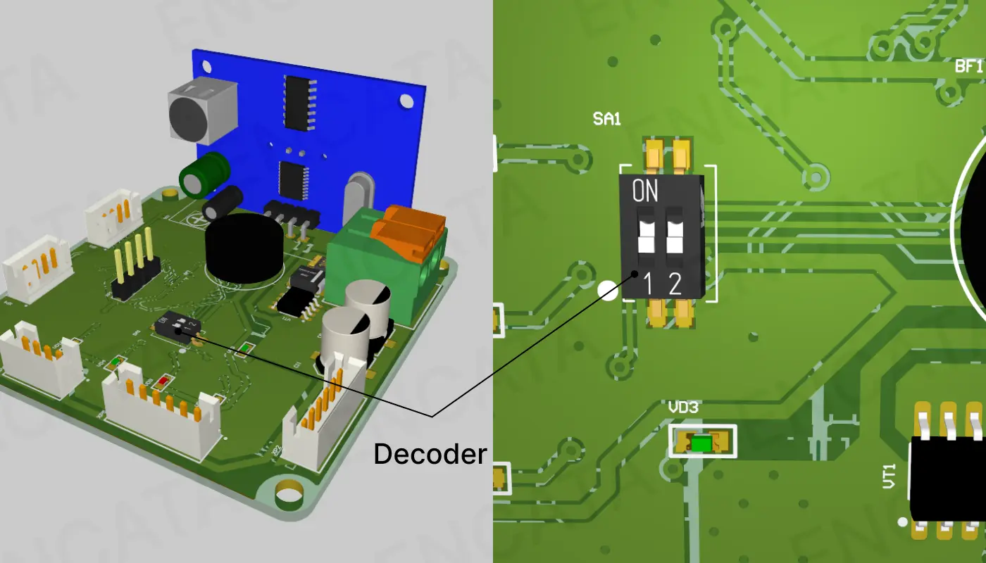
We also developed modular sensor and indicator boards. To avoid long wiring harnesses, we split the robot into four sides connected via CAN. Each side received a universal board with identical sensors. Position was assigned using a two-position hardware decoder set during assembly.
Sensor and indicator module. Decoder
Each board handled ultrasonic and optical obstacle sensors plus LED strips. Because the hardware was uniform, we created a single firmware version applicable to all sides. The master controller distinguished the boards via registers assigned by the decoder, while functions were mapped accordingly: the front board controlled white headlights, the rear handled red tail and brake lights, and the side boards implemented dynamic orange turn indicators.
This modular approach eliminated the need for four separate designs and firmwares, saving development time and simplifying debugging. Updates were applied once and automatically worked across the system.
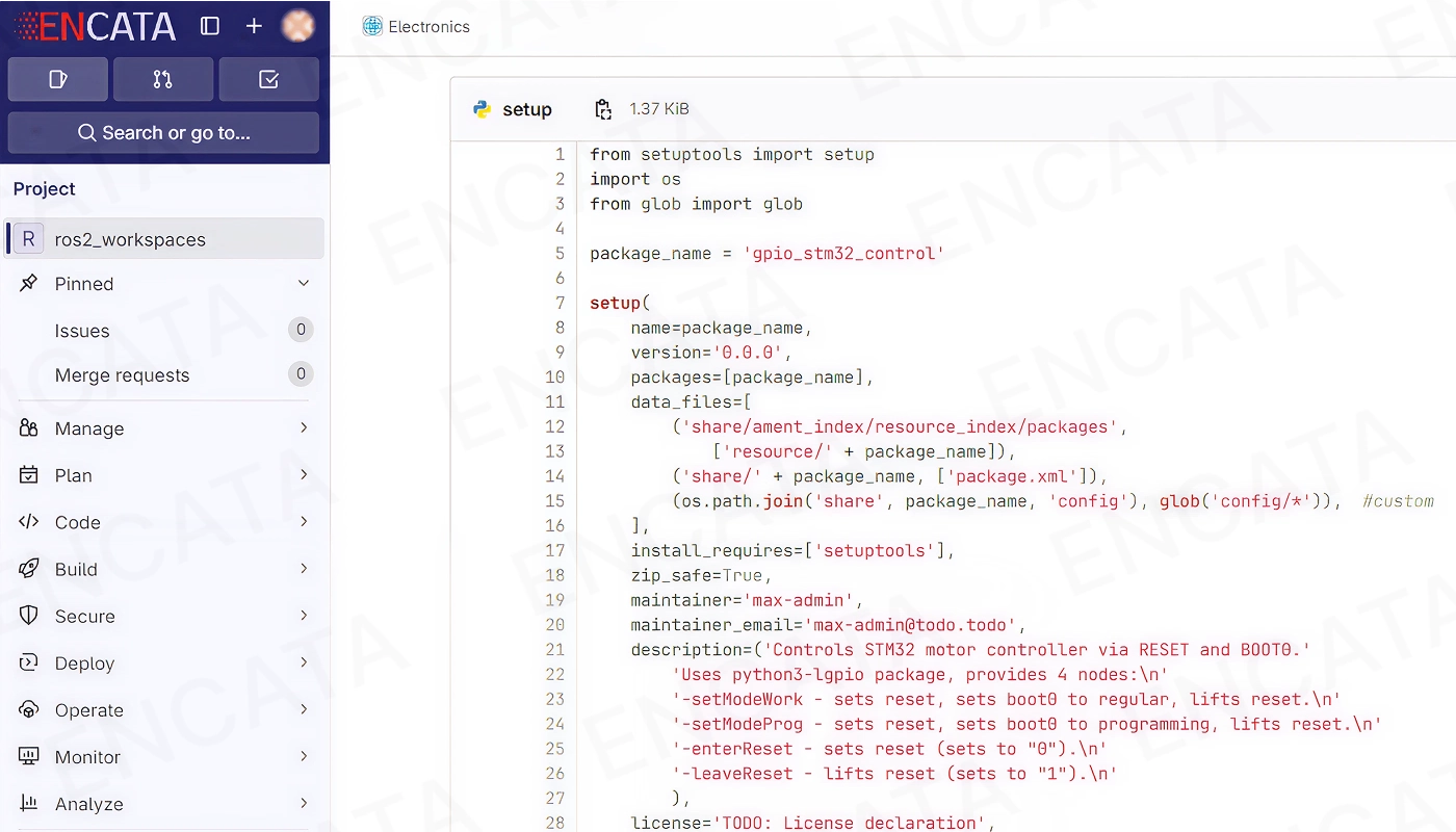
On the software side, we started with ROS 2 Humble on Ubuntu 22.04 (LTS). This let us quickly assemble and test an MVP stack. Later, we migrated to ROS 2 Jazzy (Ubuntu 24.04) to leverage improved tracing tools and optimized DDS communication, which helped us detect bottlenecks and achieve stable performance.
ROS2 code screenshot
For motor control we used ros2_control with a CANOpen driver for ZLAC8030 drives. Even though a driver was available, configuration was still demanding: we had to study CiA-301/402 standards, set motion parameters, and tune built-in PID controllers.
Initially, we planned to use MicroROS with a Step-Dir interface for motor control, but in practice this caused jerky motion and lag in responsiveness. We shifted motion control to Raspberry Pi via CAN and ros2_control, while MicroROS was retained for auxiliary tasks such as polling 16 obstacle sensors and controlling indicators. Raspberry Pi was chosen as a cost-effective MVP platform with broad ecosystem support.
For autonomous navigation, we implemented the Navigation2 stack. The robot operated in two modes: map building and path following. A behavior tree managed its actions: following routes, avoiding obstacles, and stopping when safety margins were breached.
Two key difficulties arose:
Nav2 parameter tuning. Robot behavior depends heavily on dozens of parameters (linear/rotational velocity, turning radius, obstacle avoidance). Official docs provide descriptions but no ready values for a given platform, so we ran extensive experiments to find the right balance for our robot’s dynamics.
Simulation vs. reality. While Gazebo simulations provided ideal conditions, real-world operation naturally introduced factors such as odometry noise from optical encoders and higher inertia during turns. To account for these, we refined localization and path-planning parameters so the robot performed reliably in practice.
For perception, we integrated a lidar to build maps and track obstacles in real time. The available ROS2 driver worked, but real lidar output was sparser than in simulation. We tuned data-processing algorithms to restore mapping accuracy.
Lidar-based SLAM mapping and obstacle detection: simulation environment (left) and real-time lidar data in RViz (right).
Testing and debugging ran through Gazebo and RViz with unified code for simulation and prototype, which accelerated validation. Still, Raspberry Pi 4 faced heavy load: SLAM and localization overwhelmed the CPU. We offloaded heavy processes to an external PC, leaving sensor and actuator control onboard. Communication ran via local Wi-Fi, while ROS2 abstracted node communication seamlessly.
Later, network overload became an issue. Using ROS 2 Jazzy tracing tools and Wireshark, we diagnosed duplicate message traffic between devices. The issue was fixed by optimizing node distribution across robot and PC, and tuning Cyclone DDS to minimize network overhead.
We delivered a minimum viable product – a warehouse/production robot that can already automate logistics workflows. It navigates user-defined waypoints, builds maps, finds optimal paths, and adapts routes dynamically. The working prototype proved technical feasibility and is ready for further development and scaling.
Results and Benefits
We developed and manufactured the first iteration of the LeanKey warehouse robot. The customer received a working prototype ready for industrial environment trials, along with the complete design documentation.
The prototype was successfully tested first in office conditions and later in a production facility.
If you are interested in this project and would like to contact the customer, please fill out the form below. We will forward your request.
The autonomous snooker robot is a device that serves as a trainer during a game of pool. The robot can work as a trainer, against a human, or in tandem with them. The kicking mechanism replicates a human kick's dynamics.
EnCata supported a robotics startup as an engineering contractor, developing a custom warehouse robot (400 kg load) for indoor and outdoor use — from concept to pilot-ready prototype. All IP belongs to the customer.