EnCata developed a heat chamber engineered to simulate extreme high-temperature environments. The unit heats up to 60°C with ±3°C uniformity across the full volume and features adjustable humidity control.
A company approached EnCata to design a heat chamber for a climate testing system used to evaluate firefighters' protective gear.
The core challenge was building a system that could heat air to 60°C, hold that temperature steady with ±3°C uniformity throughout the chamber, and enable precise humidity control. These specs were mission-critical for the client. They ensured accurate testing and consistent results across multiple runs.
Challenge
Rapid ramp-up to operating temperature with full-volume uniformity. The heat chamber was built for human testing in protective gear, imposing multiple interconnected requirements on the temperature profile: hitting 60°C quickly, holding steady during long-duration trials, and maintaining ±3°C uniformity across the entire working volume. These goals are naturally at odds – speeding up heating often leads to hot spots and poor distribution. Our task was to nail the ramp-up dynamics without degrading the overall temperature field.
Achieving fast heating rates without overheating elements. Hitting the target specs demanded high installed thermal power. But the heating elements had to stay within safe operating temperatures to guarantee reliability and long service life. The core engineering hurdle: delivering that power while avoiding localized overheating of the heaters and keeping temperature uniformity intact throughout the chamber.
Challenges
01
Rapid ramp-up to operating temperature with full-volume uniformity
The heat chamber was built for human testing in protective gear, imposing multiple interconnected requirements on the temperature profile: hitting 60°C quickly, holding steady during long-duration trials, and maintaining ±3°C uniformity across the entire working volume. These goals are naturally at odds – speeding up heating often leads to hot spots and poor distribution. Our task was to nail the ramp-up dynamics without degrading the overall temperature field.
02
Achieving fast heating rates without overheating elements
Hitting the target specs demanded high installed thermal power. But the heating elements had to stay within safe operating temperatures to guarantee reliability and long service life.
The core engineering hurdle: delivering that power while avoiding localized overheating of the heaters and keeping temperature uniformity intact throughout the chamber.
03
Approach & Solution
A company approached EnCata to design a heat chamber for a climate testing system used to evaluate firefighters' protective gear.
The core challenge was building a system that could heat air to 60°C, hold that temperature steady with ±3°C uniformity throughout the chamber, and enable precise humidity control. These specs were mission-critical for the client. They ensured accurate testing and consistent results across multiple runs.
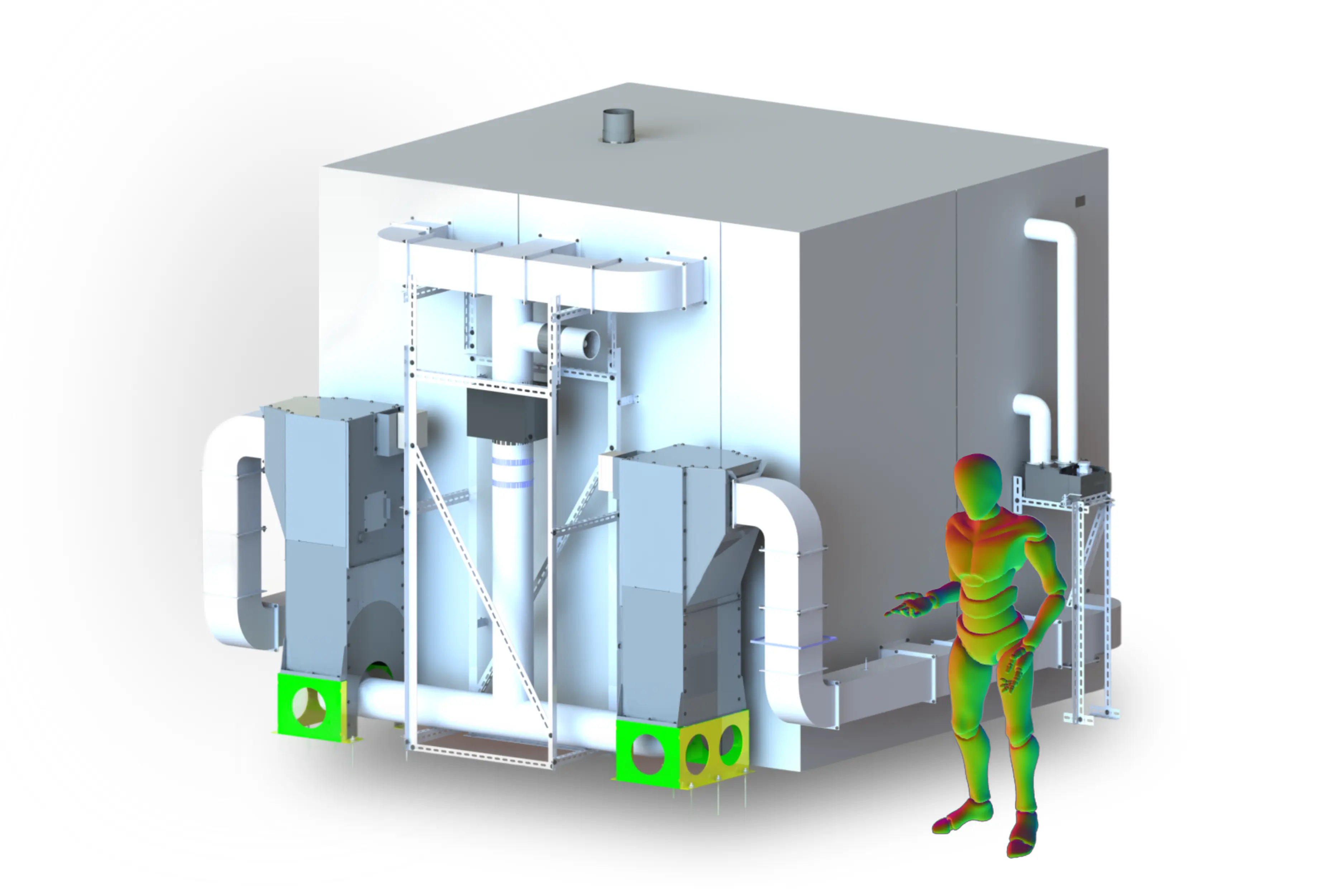
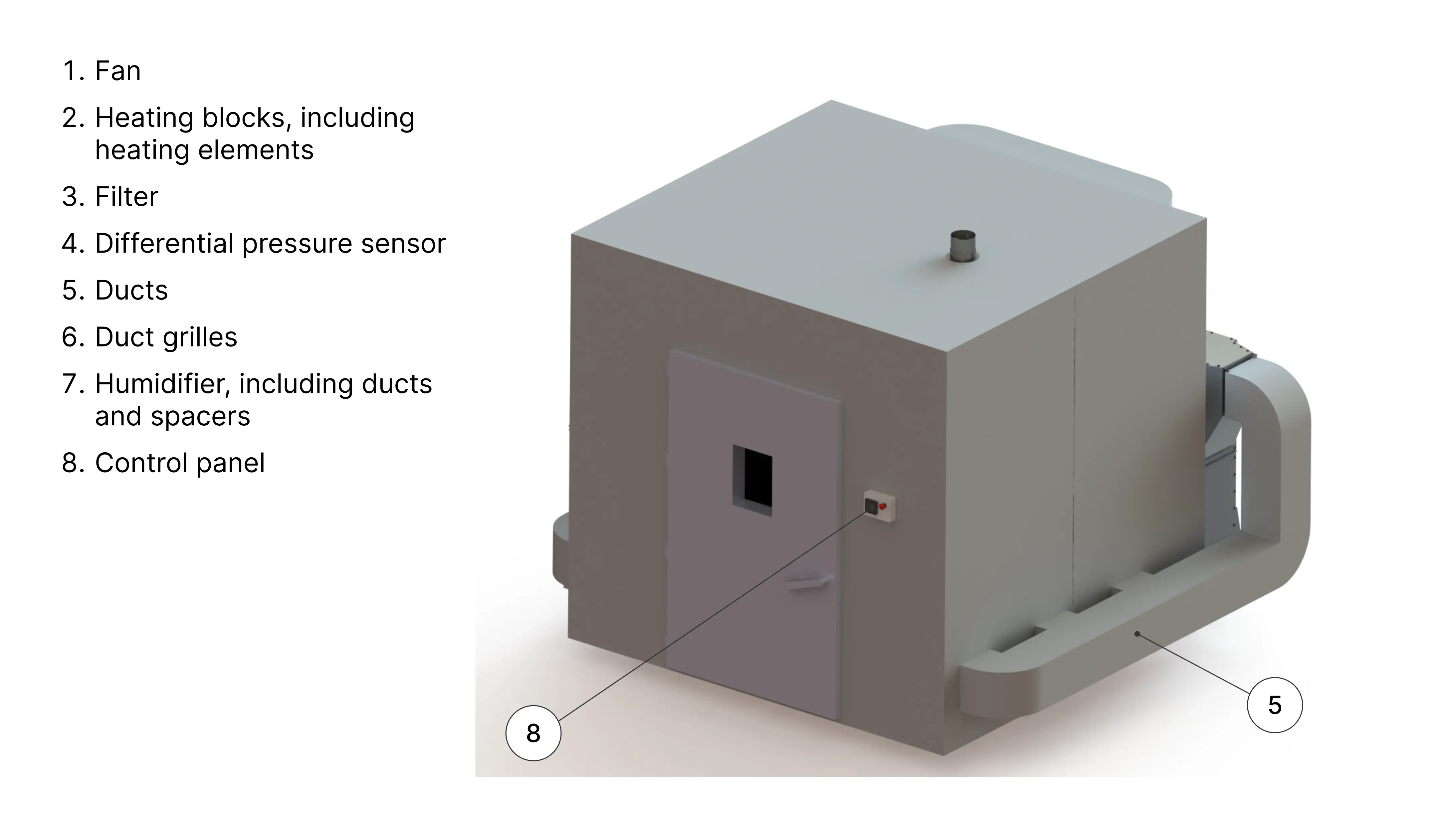
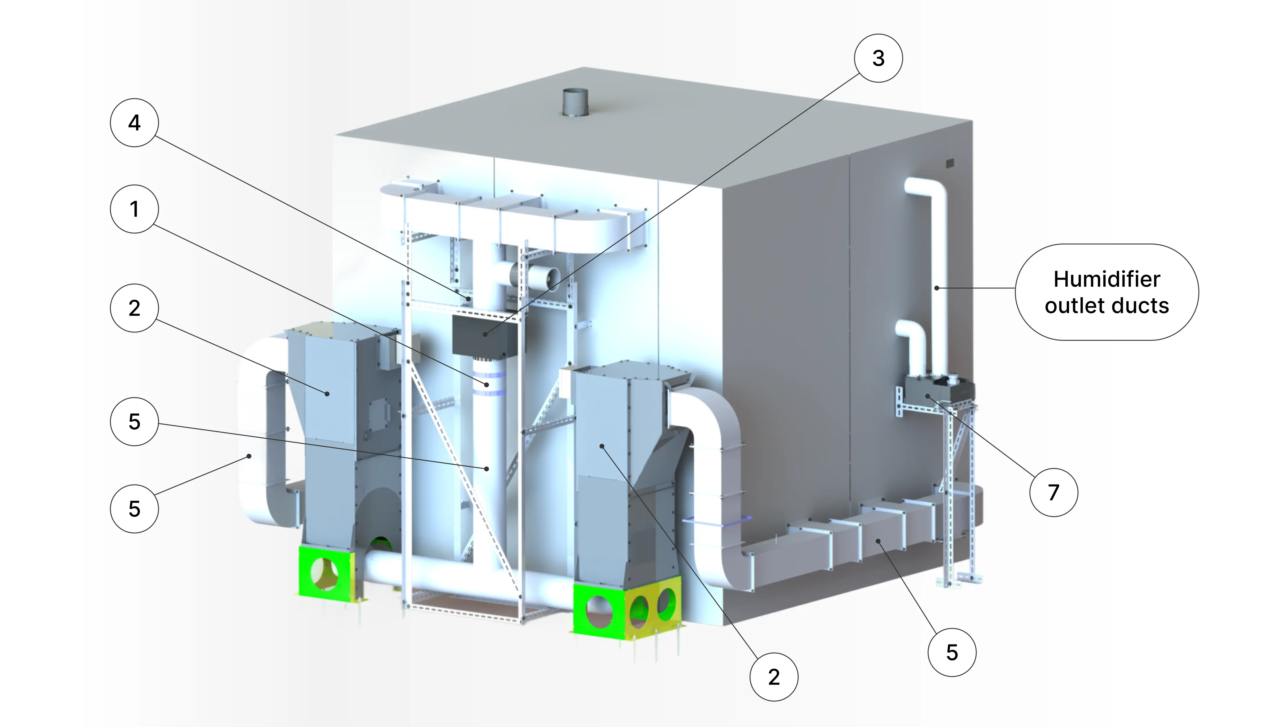
To give you context as we walk through the development process, we'll start by showing the final chamber layout and key components (see Figures 1 and 2).
Figure 1. The front view of the heat chamber
Figure 2. The rear view of the heat chamber
Initial development: Calculations and modeling
Development of the heat chamber for the test complex began with comprehensive calculations. At this early stage, the team had yet to settle on a specific layout. We understood the target parameters and constraints, but the central question remained: which architecture would reliably meet them?
The chamber needed to heat air to 60°C while maintaining ±2–3°C uniformity throughout the working volume. Designed for human trials in protective gear, it had no room for hot spots, uneven airflow, or operational instability.
General view of the climate complex
Engineers built an initial model around closed-loop air recirculation, using a single high-temperature fan and a unified heating block. Air was drawn from the chamber, passed through the heater, and recirculated to evenly raise temperatures across the volume. The simulation accounted for practical details, including chamber dimensions, PIR panel properties, duct insulation, and the single-pane observation window, which added to overall heat losses.
Closed-Loop Air Recirculation System (3D Render)
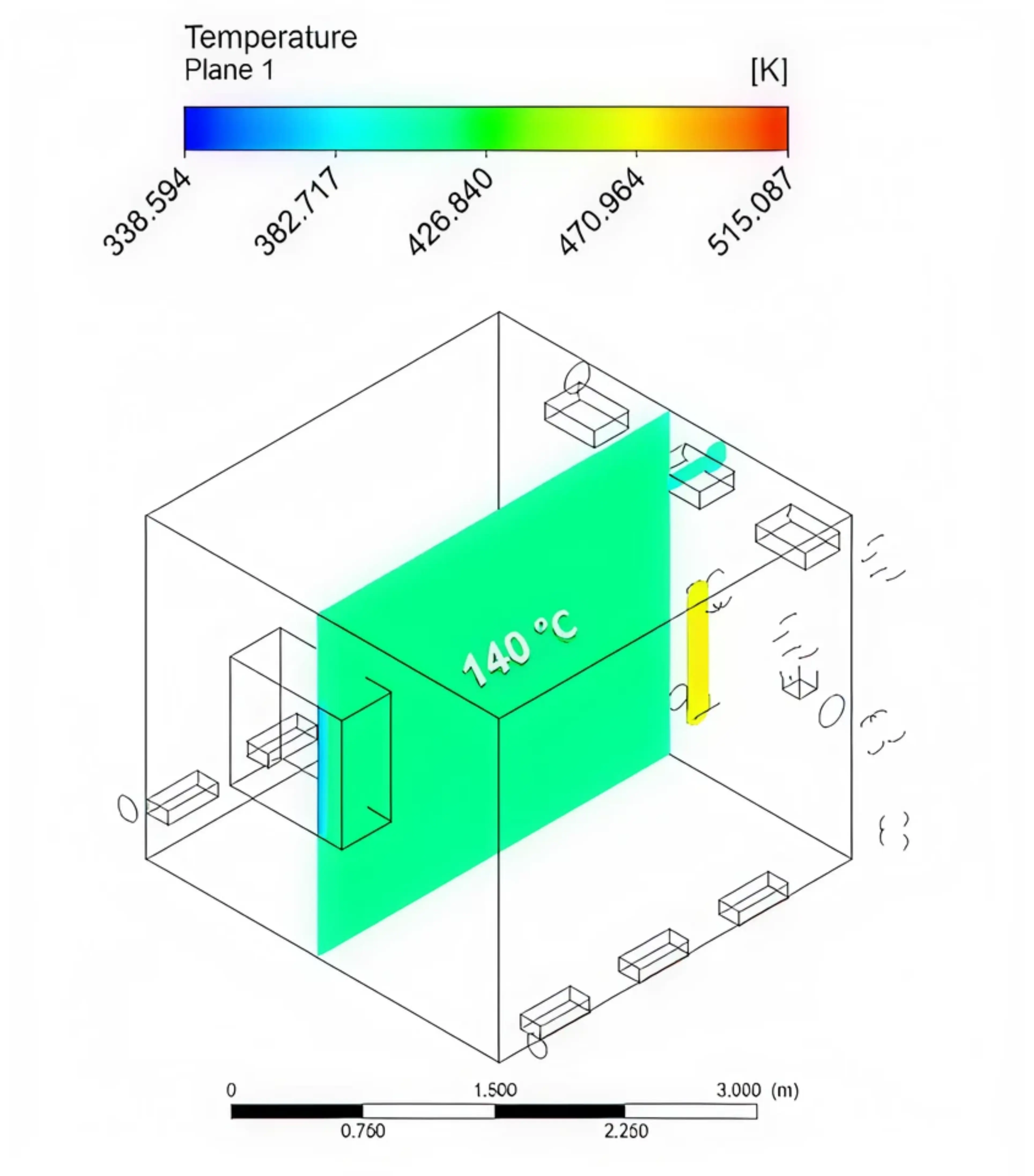
Thermodynamic modeling showed solid predictability for temperature distribution. In the central plane, the field stayed even, with point-to-point deviations under ±1°C. From a uniformity standpoint, the approach looked stable and controllable.
Temperature distribution diagram in the mid-section
Heating rate analysis
The calculations highlighted a key limitation: ramp-up speed. With 2400 W heating power, the chamber took about two and a half hours to reach the target temperature – a timeline that fell short of client requirements and would limit the test complex's operational throughput.
The natural next step was to scale up the heating capacity. At 6000 W, the chamber hit 60°C in under an hour, fully meeting the time constraints and achieving a critical benchmark.
Addressing heater overheating
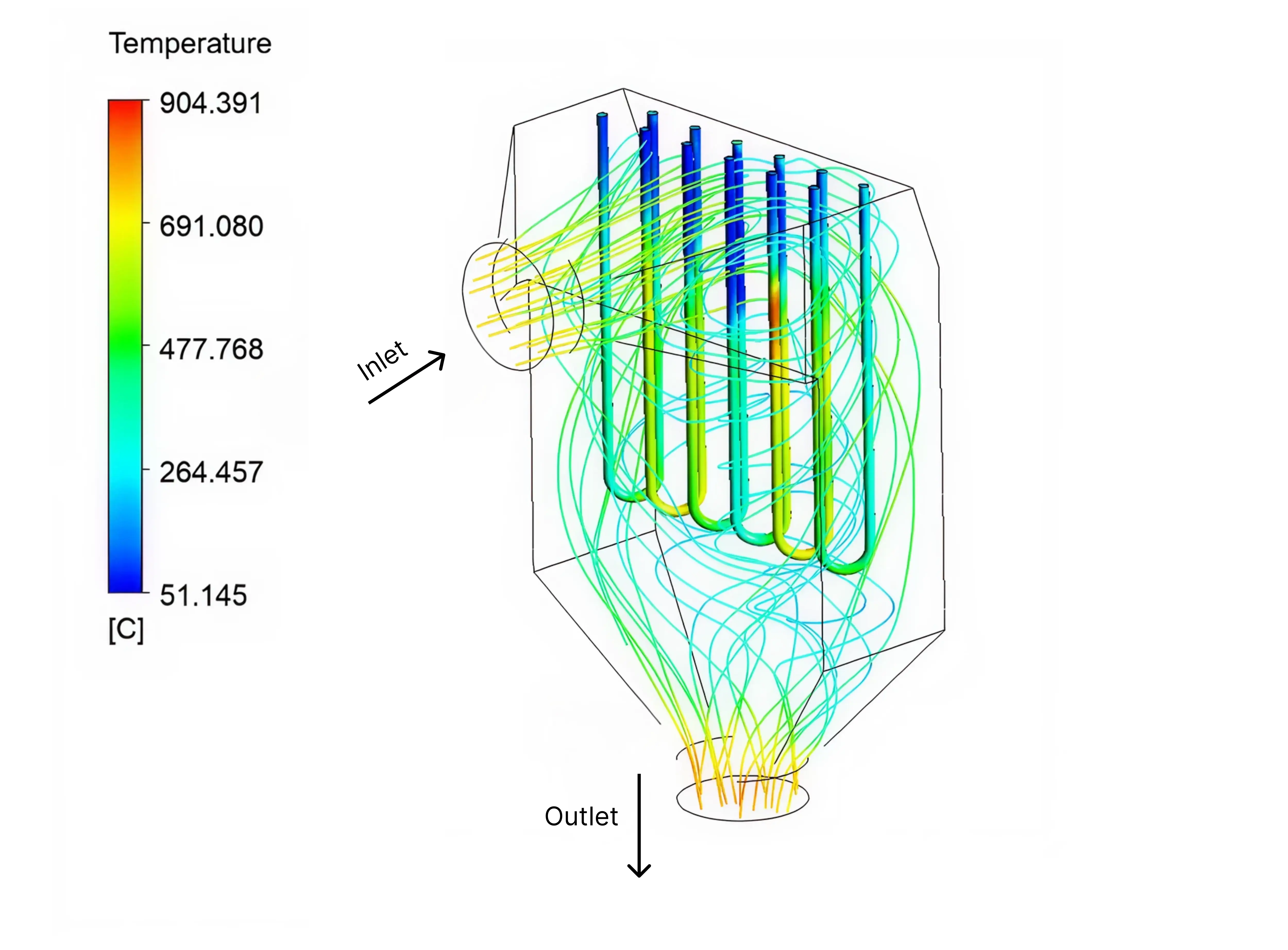
Further analysis, shifting from chamber-wide temperatures to heater sheath surfaces, revealed localized overheating in the single 6000 W block: element sheaths reached ~900°C in simulations. This wasn't a systemic design flaw, but rather a manageable thermal concentration that called for targeted reconfiguration.
Inlet and outlet air flow trajectories on heater surfaces (6000 W block)
Rather than pursuing custom heaters or cutting power (both at odds with the specs), the team refined the heating block layout: splitting it into two independent 3000 W units. This preserved total thermal output, enhanced airflow around the elements, and brought peak sheath temperatures down to under 360°C – nearly half the safe operating limit.
Effective heat chamber design hinges on how thermal loads are distributed across heating elements. Using multiple independent heating blocks, instead of a single high-power unit, helps spread the load evenly, reducing hotspots, improving airflow around elements, and significantly extending equipment service life.
Chamber design and construction
In parallel with architecture selection, we honed the chamber's structural design. It was built as a fully insulated enclosure from sandwich panels secured with eccentric locks.
Sandwich panels with eccentric locks
This approach delivered not only excellent thermal insulation but also resilience to cyclic temperature stresses – no seam cracks or warping, which is vital for test rigs enduring repeated heat/cool cycles. Wall thickness came in at 100 mm, optimized via heat loss and mechanical strength analyses. The ribbed metal sheeting enhanced panel stiffness by boosting the moment of inertia, allowing us to skip additional bracing and maintain a streamlined build.
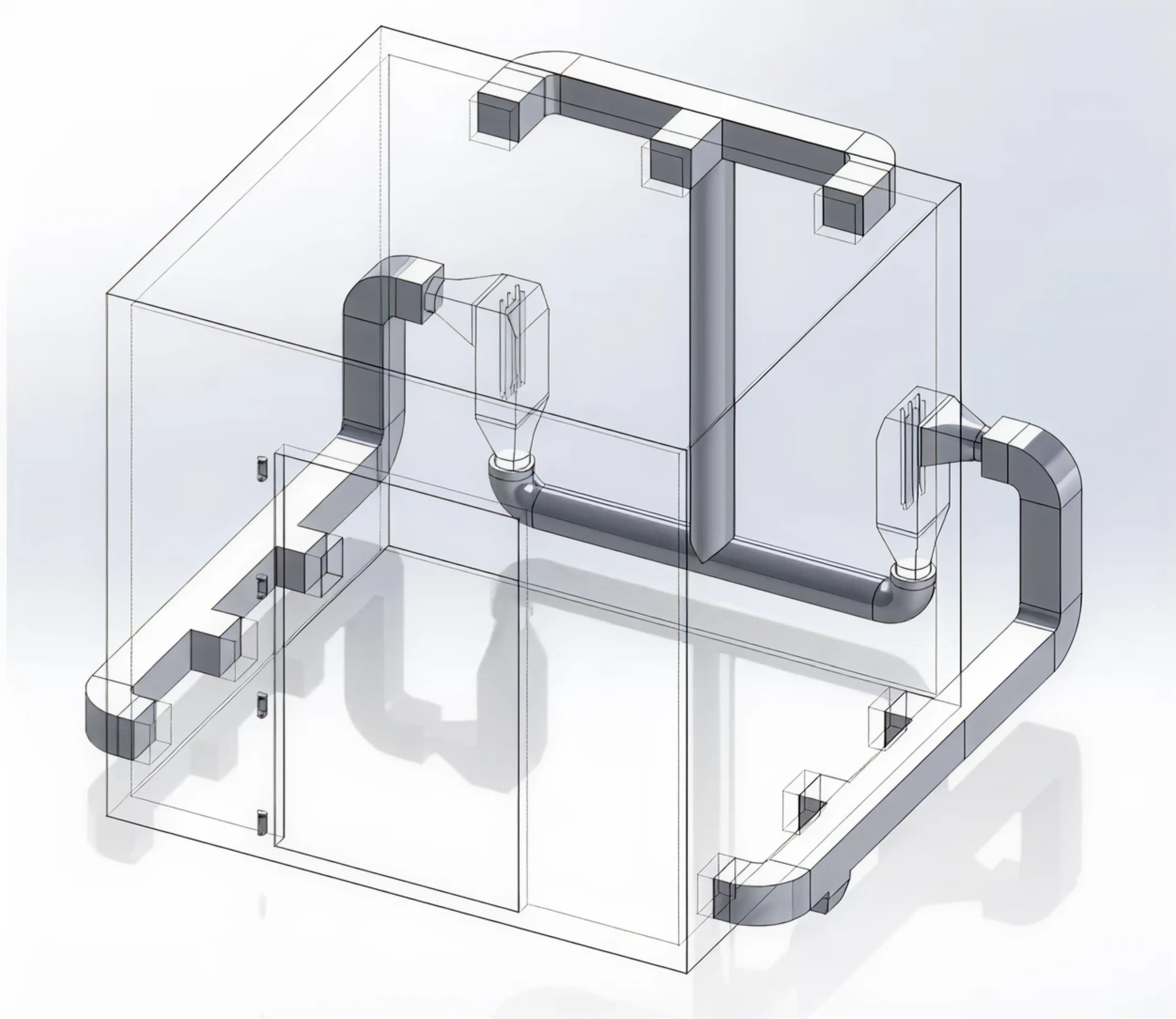
Air circulation and filtration
The airflow scheme required careful attention. The heat chamber uses a closed-loop supply-exhaust system driven by mechanical recirculation: air is pulled from the upper zone (where the hottest volume collects), routed through filtration and heating sections, and reintroduced via lower supply grilles. This configuration harnesses natural convection as a supporting mechanism, promoting even temperature distribution from top to bottom.
Air filtration was a built-in priority. Human trials in protective gear mean the airstream carries fabric fibers, dust particles, and contaminants, any of which could spark localized heater overheating or ignition risks. That's why filter status monitoring and a differential pressure sensor are integral, ensuring both safety and operational reliability.
Manufacturing and assembly
With the computational model finalized and the layout validated through simulations, the project moved into manufacturing and assembly.
The heat chamber was designed for assembly from standard, readily available off-the-shelf components. Its frameless structure relied on self-supporting sandwich panels, produced by a contractor to our detailed engineering drawings. These served dual roles as both enclosure and load-bearing elements. This deliberate choice aligned perfectly with client expectations, delivering full spec compliance without added complexity, budget creep, or extended approval timelines.
The bulk of engineering effort focused on integrating all functional subsystems inside the chamber. Even using off-the-shelf ventilation components, the team handled custom assembly and modifications. Pipes, elbows, plenums, and grilles were procured separately, then cut into the chamber shell and tailored to match required airflow cross-sections for optimal volume rates and temperature profiles.
A major challenge was routing the ducts through the chamber frame without introducing extra heat losses. We addressed this by insulating all hot air supply and return sections with mineral wool, wrapped in foil-faced barriers. This not only minimized losses but also prevented condensation on cooler duct runs during high-humidity operations.
Inside-chamber supply grilles required special attention. Fabricated in-house and equipped with manual dampers (no automated actuators), they allowed hands-on airflow balancing prior to commissioning. Manual adjustment of these grilles enabled us to equalize resistance across different zones and ensure uniform warm air distribution throughout the volume.
Interior View
Humidifier integration
Humidity control emerged as a requirement midway through the project. Initial assessments and the technical spec hadn't accounted for it, so neither calculations nor the chamber architecture included a humidifier from the start. When the client specified it, we had to integrate a solution within the existing design.
Treated as an add-on to the air circulation system, the humidifier drew on the team's prior experience with similar setups. We proposed a proven configuration right away – no CFD simulations or prototype trials needed: the unit was isolated from the main thermal loop and fitted with its own active airflow via a compact dedicated fan on the outlet duct. This fan forced air through the humidifier, delivering a steady stream of moistened air directly into the chamber via a separate pipe.
This setup kept humidifiers entirely self-sufficient – free from the duct flows, which prevented condensation risks, and ensured reliable humid air delivery to the working volume. Initial tests confirmed it hit the targets perfectly, fully satisfying the client with zero revisions.
In climate control systems, equipping components with dedicated active airflow for independent local circulation ensures rock-solid reliability. For the humidifier, a compact fan on the outlet duct guaranteed consistent humid air delivery without relying on the main ventilation loop, eliminating condensation and leak risks. This solution nailed the humidity targets and offers a versatile approach adaptable to other subsystems for uninterrupted performance in any operating mode.
External View from Humidifier Side
On-site assembly
Heat chamber assembly was carried out directly at the client's facility. Sandwich panels were erected by a contractor based on our engineering documentation, followed by our team's internal integration work: installing the ventilation system, heating blocks, humidifier, and control elements. This stage naturally involved fine-tuning refinements, correcting minor mounting discrepancies, and site-specific optimizations that couldn't be fully anticipated from upfront calculations alone.
Results and Benefits
The project is completed. We engineered, manufactured and assembled the heat chamber for the test complex, managed commissioning, and trained operators. Delivered to the client:
prototype heat chamber;
3D model of the enclosure;
complete engineering documentation package;
test chamber operation manual.
Important: We don't sell off-the-shelf heat chambers. If this solution piques your interest, we can build a custom version tailored to your needs. Simply fill out the contact form below.
EnCata developed a control cabinet that manages a heat chamber (60 °C heating, humidity, ventilation, safety) and integrates a cold chamber and chiller via RS-485 for one of its customers. The cabinet is part of a climate system designed for simulating extreme temperatures for firefighters.
EnCata engineered a custom tire pressure sensor (TPMS) test stand for industrial QA—developing mechanics, electronics, and firmware from scratch. The compact device supports 10 chambers. All IP belongs to the customer.


%202.webp)


