Buckle up for a short, easy-to-digest piece that introduces different motion transmission mechanisms. The article covers brief overviews, use cases, and key characteristics to keep in mind.
If you’re developing a new device (e.g. consumer electronics, medical equipment, or an automated system) you’ll eventually face a question: how will motion be transmitted inside the assembly?
To clarify terms: motion transmission is how one part of a mechanism makes another part move. Your choice of transmission method affects:
device layout;
dimensions and weight;
power consumption (via efficiency);
assembly and maintenance cost;
reliability and service life.
This article doesn’t catalog every possible transmission – only the most common ones.
If you’re on a product team without a formal engineering background, this guide should help. It explains motion transmission types in plain terms so you can better follow what your contractor is doing, check that it’s appropriate, and write clearer requirements.
Core Motion Transmission Methods
We’ll cover five of the most common approaches. For each, you’ll get the working principle, product examples, and cues that indicate when that transmission is a good fit. That way, you can decide what belongs in your device requirements.
Gear Drive (Gears)
A gear drive transmits rotation between shafts through rigid tooth engagement. The smaller gear (the pinion) drives the larger gear (the wheel), changing speed and torque at the output shaft. The gear ratio stays constant, enabling slip-free, predictable power transfer.
Note. The gear ratio is the ratio of input to output rotational speeds. If the input spins fast and the output spins slower but with higher torque, the ratio is said to be “high.”
Strengths. Gears are compact (micro-motors, precision actuators), can transmit high power (industrial gearboxes, machine tool drives), and support high speeds (fans, motorized spindles). Their constant ratio and high efficiency make them ideal where motion must be stable and predictable (watch movements).
Limitations. Gears don’t span long distances between shafts (e.g., spaced conveyor rollers), are rigid (little vibration damping), can be noisy if poorly manufactured (older industrial gearboxes), and need regular lubrication.
Where and why gears are used:
Electric locks – fixed-angle, slip-free motion is essential for reliable actuation.
Appliance gearboxes (blenders, meat grinders) – reduce motor speed and increase torque to do mechanical work.
Watch mechanisms – synchronous motion with minimal backlash keeps the hands moving evenly.
Sewing machines – synchronous rotation with low (acceptable) backlash for needle timing.
Industrial reducers – lower speed while boosting torque.
You must reduce speed and increase torque to convert motor power into useful work (e.g., grinders, industrial reducers).
Minimal package volume between shafts (e.g., locks, compact appliance drives).
Nearly backlash-free, synchronous motion is important (e.g., clocks, timers, precision toys).
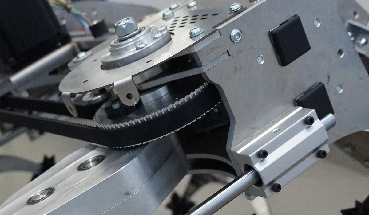
Belt Drive
A belt drive uses two pulleys mounted on shafts and a belt that wraps around them. Motion is transmitted by friction between the belt and pulleys created by belt tension.
Two common types:
Timing (toothed) belt – synchronous rotation with minimal slip.
V-belt – allows limited slip, protecting the motor during peak loads
Strengths. Belts can span relatively large distances between shafts (fans, conveyors). They run smoothly and quietly (e.g., printers), absorb load fluctuations thanks to belt elasticity (sewing machines), and allow protective slip under overload (small appliances). The design is simple and needs no lubrication.
Limitations. Pulleys occupy more space than gears (consider in industrial drives). V-belts can lose synchrony due to slip (small motors, printer carriages). High belt tension increases loads on shafts and bearings (conveyors, grinders). Belts wear and require periodic replacement.
Where and why belts are used:
Printers (timing belt) – smooth carriage motion for accurate print lines.
Fans and HVAC – quiet, low-vibration coupling from motor to impeller.
Conveyors & hoists – transmit motion across distance and to multiple elements, smoothing overloads.
Small appliance motors – protect motors from overload by allowing controlled slip.
Signs you likely need a belt drive:
Motion must be transmitted across relatively large shaft spacing.
You need smooth, quiet motion with minimal vibration.
Overload protection is desired during sudden load changes.
Absolute rotational accuracy isn’t critical (minor slip acceptable) and the above points hold.
Low-maintenance operation without lubrication is preferred.
Chain Drive
A chain drive transmits rotation from the driving shaft to the driven shaft via a chain that engages sprocket teeth. Because the chain links positively engage the teeth, there’s no slip and speed remains constant. Chain drives can transmit high forces, span larger distances without the slip that can affect belts, and drive multiple shafts simultaneously (conveyors, lifting systems). They also require less tension than belts at high loads and support high ratios.
Limitations. Chain links and joints wear due to repeated tooth contact, so regular lubrication and maintenance are required. Chains generate noise and dynamic loads.
Where and why chains are used:
Bicycles – transmits pedal force to the wheel over a distance unsuitable for gears; V-belts could slip.
Weight-stack gym machines – stable motion under changing loads across multiple transfer points; belts could slip.
Conveyors & feeders – drive several shafts at once over distance; gears are too short-range, V-belts unreliable at high load.
Industrial reducers – transmit rotation with high loads and high ratios where shaft spacing rules out gears and belts may slip.
Signs you likely need a chain drive:
Long center distances between shafts (conveyors, hoists).
Positive, slip-free torque transfer under variable load (bicycles, gym machines) and the distance requirement above.
One input must drive several shafts with equal speed/force distribution (industrial feeders).
High load and large transmission ratio requirements.
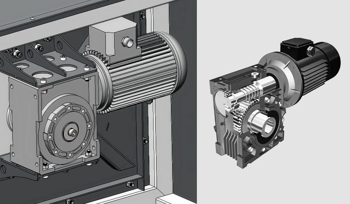
Worm Gear Drive
A worm gear uses a screw (worm) driving a worm wheel at 90°. Relative sliding between teeth lowers efficiency and increases wear, but yields smooth, quiet motion, very high reduction ratios, and self-locking: under certain geometries, the wheel cannot back-drive the worm.
Strengths. Large ratios in compact form, smooth and quiet operation, accurate motion transfer, positional holding without separate brakes (self-locking when design conditions are met).
Limitations. Lower efficiency, higher wear and potential for galling, higher material cost (worm/wheel materials), and the need for proper lubrication (more of a requirement than a limitation, but must be planned).
Worm gear applications:
Powered recliners – backrest holds position after you release the button thanks to self-locking.
Gate operators – slow, high-force motion; gates don’t roll back due to high ratio and self-locking.
Lift reducers – slow, high-torque motion for raising loads.
Medical tables & equipment – smooth motion with stable holding at set positions.
Signs you likely need a worm gear:
Slow motion with high torque (recliners, lift platforms).
The mechanism must hold position at rest without a separate brake (self-locking).
Smooth, quiet motion at low speeds with good kinematic accuracy.
Very high reduction ratio and low output speed (gate operators, lifting mechanisms).
Pneumatic Actuation (Pneumatic Cylinder)
A pneumatic cylinder operates by admitting compressed air to one chamber to push a piston. The piston is connected to a rod that does mechanical work. Motion is linear and fast, with quick response to air flow changes.
Strengths. High-speed, repeatable strokes; simple control without complex electronics; oil-free operation in clean environments; easy to tie into a plant air system.
Limitations. Available force is limited by air pressure and piston area (unsuitable for very heavy loads). Requires clean, dry air; without filtration, sticking and accelerated wear are likely. Positioning accuracy is limited: precise stops are typically achieved with hard stops at end positions; precise mid-stroke stopping is not practical without special measures.
Where and why pneumatics are used:
Automatic dispensers – fast, sharp strokes deliver accurate doses thanks to high speed and instant response.
Packaging machines – rapid clamping/pressing for reliable closure.
Food-industry pick-and-place – high speed and repeatability maintain throughput.
Sorting/feeding machines – quick, repeatable linear motions at high cycle rates.
Signs you likely need pneumatics:
You need fast, straight-line strokes (e.g., firm lid closure on a packaging line).
High-frequency, repeatable cycles where each cycle must match the last.
Operation in clean or aggressive environments where lubricants are undesirable and the speed/repeatability above are required.
Hydraulic Actuation (Fluid Under Pressure)
A hydraulic cylinder uses pressurized fluid acting on a piston. Fluid flows through hydraulic lines to push the piston and rod, producing smooth, powerful linear motion. Flow controls speed; pressure sets force. Because hydraulic fluid is (effectively) incompressible, hydraulics can move and hold heavy loads.
Strengths. Accurate linear motion, smooth movement of heavy loads, and load-holding via valves and circuit design. Excellent for high forces with controlled speed (moving heavy objects smoothly and safely).
Limitations. Systems are heavy and complex: pump, valves, lines, seals – all must be tight and well maintained to avoid leaks and premature wear. Hydraulic oil also requires cleanliness management.
Where and why hydraulics are used:
Automotive lifts – raise and hold vehicles; incompressible fluid provides compact high force and holding.
Presses – generate strong, controlled compression without damaging parts.
Hydraulic claws/grapples – grip and hold heavy items with precise force control and stable positioning.
Construction machinery (excavators, loaders) – move booms and buckets with high force and controllable speed.
Signs you likely need hydraulics:
Smooth, controllable linear motion under heavy load (vs. pneumatics, which are fast and less smooth).
Load-holding at rest (fluid rigidity and circuit valves keep the rod/ load in place; pneumatics cannot hold as rigidly).
Very heavy objects or very high forces.
Precise control of speed and force for safe, smooth motion (pneumatics struggle to hold mid-stroke positions accurately).
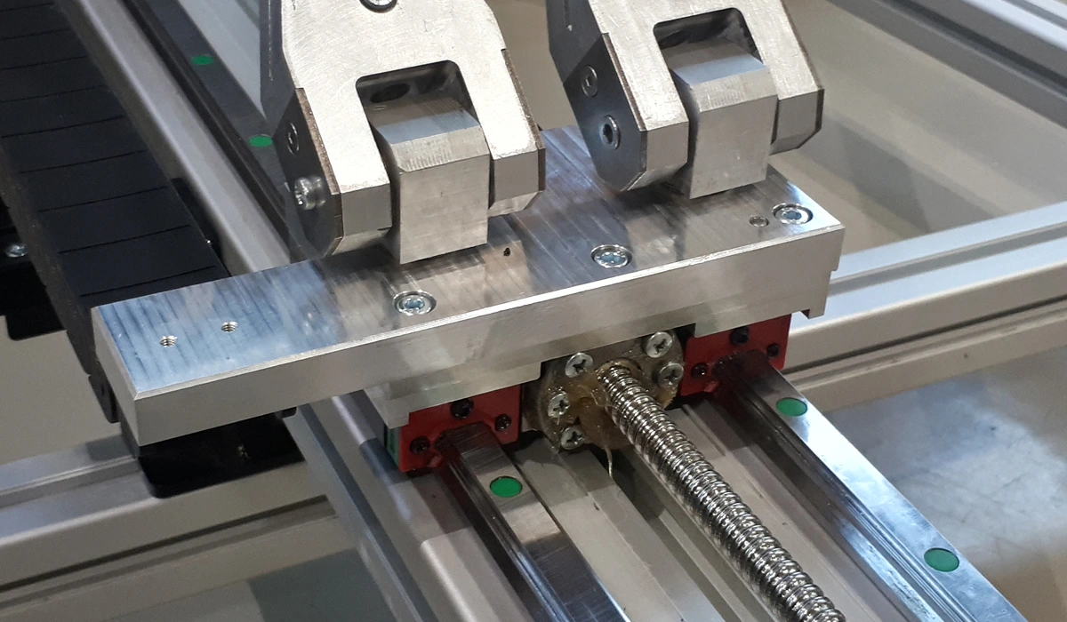
Ball Screw (Ballscrew)
A ballscrew converts rotary motion to linear motion with high precision. Balls roll in helical grooves between screw and nut, transmitting force without slip. As the screw turns, balls drive the nut and then recirculate through return channels. Preload can be applied to remove backlash, increasing axial stiffness and positioning accuracy.
Strengths. High axial force capacity (e.g., up to ~10 kN in compact forms), repeatability on the order of ±0.01 mm, minimal backlash (≤0.02 mm), critical for precision machining, industrial 3D printing, and robotics. Low friction losses (efficiency ≥ 0.9), compact for the load capacity, and long life (millions of cycles).
Limitations. Screw and nut take space and require proper mounting; return channels must be protected from contamination. Tight manufacturing tolerances are essential. Poor quality leads to backlash or premature wear. Installation and use must follow the manufacturer’s guidance (not a flaw per se, but a real requirement).
Where and why ballscrews are used:
CNC machines – precise table or tool positioning with minimal backlash (superior to belt or chain for accuracy).
Industrial-grade 3D printers – accurate XYZ positioning with better stability than belts/chains/pneumatics.
Robotics – linear actuators or joints needing high axial stiffness and significant force; belts/chains can’t hold accuracy under load.
Signs you likely need a ballscrew:
Convert rotation to linear motion with very high accuracy and repeatability (backlash ≤ 0.01–0.02 mm). Belts, chains, hydraulics, pneumatics, and worm drives can’t match this combination of accuracy and load handling.
High axial forces in a compact package. Ball contact carries load efficiently.
Durable, predictable linear motion over millions of cycles. Belts/chains wear faster; hydraulics are durable but more complex to maintain; pneumatics are durable but limited in force.
Master the distinction between computer vision and machine vision. Discover which solution, custom or COTS, fits your machine vision project needs best.
Software Development
AI/ML
Big Data
4 Mistakes that Machine Learning Startups Do
This article speculates on the common mistakes made by machine learning-based startups. If you're part of one, be sure to check it out!
Product Development
Engineering
The Ultimate Guide to Transferring the Model from CAD to CAM
New to CAD or CAM? This guide covers key steps for smoothly transferring models, with tips and best practices for a seamless design-to-manufacturing process.
Have a project to do?
Fill out the form and a member from our sales team will get back to you
Thank you! Your request has been submitted! We shall contact you shortly
Oops! Something went wrong... Try to reload this page and resubmit
FAQ
At EnCata, what kinds of contracts do you use? Is it a fixed-term or an agile contract?
Can you provide me with a certification of competence?
What level of training do your specialists have?
Is it possible for us to cooperate with EnCata’s team?
Is it possible to discuss the project with your technical team?
Can EnCata facilitate mass production?
Do you sign NDAs?
Patent or Develop first?
Does EnCata outsource electronics services?
Do you write program code, either software or firmware?
Are there hardware engineers in your team?
What should I do now that I've approached you with my project idea?


.jpg)


